Blog
The Ultimate Guide to TB6612FNG

In the electronic design competition, the motor drive module is a frequently required electronic component, which is used for the motion control of intelligent small vehicles. Besides, it is also widely applied in industrial equipment, household appliances and smart hardware fields.
How powerful can the tiny TB6612FNG motor driver module be? Its function should not be underestimated. If you are working on a small car project, it is one of the core components of this project. The current flowing through the pins of the microcontroller is usually only a few tens of milliamperes, which is insufficient to directly drive the motor. Therefore, the motor drive chip is generally controlled by a microcomputer to operate the motor. Next, this article will take you on a deep dive into the motor drive module — TB6612FNG.
What is the TB6612FNG motor driver?
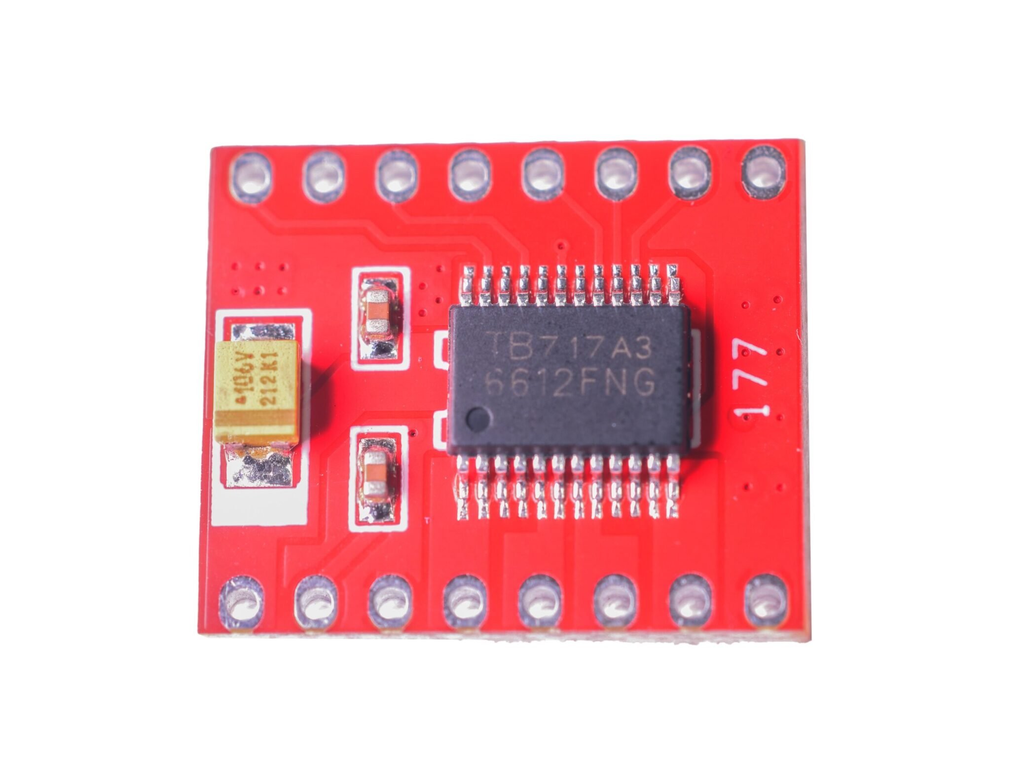
TB6612FNG is a DC motor driver device with a large current MOSFET-H bridge structure and dual-channel circuit output, capable of driving 2 motors at the same time. It has a high degree of integration and can provide sufficient output capacity. It also has advantages in terms of operating performance and energy consumption. Therefore, in integrated and miniaturized motor control systems, it can be used as an ideal motor driver device.
TB6612FNG Structure and Working Principle
This module controls the motor speed through PWM signals, and then controls the motor direction through two logic input pins.
1、H-bridge circuit structure
The TB6612 integrates two sets of H-bridge circuits (each bridge contains 4 MOSFET) internally. By controlling the on-off of the MOSFET to switch the current direction, it enables the motor to rotate forward, reverse, stop and brake.
- Direction control: The motor direction is controlled by the AIN1, AIN2, BIN1 and BIN2 pins.

2、PWM Speed Control
- Speed Control: Input PWM signals through the PWMA and PWMB pins to control the speeds of motor A and motor B respectively. The higher the duty ratio of the PWM signal, the higher the average voltage of the motor and the faster the rotational speed.
3、Logic Control Interface
The VM (motor power supply) and VCC (logic power supply) are designed separately, supporting wide voltage input. The STBY pin needs to be set to a high level to start the module. Otherwise, the output will be forcibly shut down.
TB6612FNG Schematic Diagram

The 12V pin here is actually the VM pin. The voltage range is 2.5V to 13.5V, and 12V is usually used.
Note: If VM is 12V, to avoid damaging or exploding the tantalum capacitor of the TB6612 module, it is recommended to choose a 106V tantalum capacitor. The voltage code V indicates that the rated voltage of the tantalum capacitor is 35V. Half of the rated voltage is 17.5V, which has more than half of the margin compared to 12V. (The common tantalum capacitor for the module is 476C, and the voltage code C indicates that the rated voltage of the tantalum capacitor is 16V, which is prone to damage.)
TB6612FNG Feature
- The working voltage range is wide, ranging from 2.5V to 13.5V.
- Dual channel output, capable of driving two DC motors at the same time.
- The maximum continuous driving current for each channel is 1.2A (peak 3.2A).
- The module is internally equipped with a low voltage detection and overheat protection circuit.
- In the standby mode, the internal circuit will be disconnected to reduce power consumption.
- The PWM frequency can be set within a wide range (1kHz – 100kHz).
- Small in size (24mm × 15mm), it is convenient for installation.
Pin Functions and Wiring Methods
TB6612FNG Pin Functions

| Pin | Definition |
| VM | This is where you provide power for the motors (2.5 V to 13.5 V). |
| VCC | This is the voltage to power the chip and talk to the microcontroller (2.7 V to 5.5 V). |
| GND | Power ground terminal. |
| STBY | Control input for normal operation / standby state. Set 0 for standby mode, set 1 for operation mode. |
| MOTOR A | |
| PWMA | PWM signal input terminal, the pin for controlling the speed of MOTOR A. |
| AIN1 | Motor control mode input terminal (forward rotation / reverse rotation / stop). |
| AIN2 | Motor control mode input terminal (forward rotation / reverse rotation / stop). |
| AO1 | Motor drive output terminal (controlled by AIN1 and AIN2). |
| AO2 | Motor drive output terminal (controlled by AIN1 and AIN2). |
| MOTOR B | |
| PWMB | PWM signal input terminal, the pin for controlling the speed of MOTOR B. |
| BIN1 | Motor control mode input terminal (forward rotation / reverse rotation / stop). |
| BIN2 | Motor control mode input terminal (forward rotation / reverse rotation / stop). |
| BO1 | Motor drive output terminal (controlled by BIN1 and BIN2). |
| BO2 | Motor drive output terminal (controlled by BIN1 and BIN2). |
Notice: Highlighted points! The power cord must not be connected in the wrong direction. Otherwise, the TB6612 will be damaged.
TB6612FNG Wiring Methods

Here, STBY can directly be connected to either 3.3V or 5V, and it will remain in the “1” state. Subsequently, the motor stop operation will be controlled through IN1 and IN2.
TB6612FNG Parameters
| Driving Voltage VM | 2.5V to 13.5V |
| Logic Input Voltage VCC | 2.7V to 5.5V |
| Working Current | 1.2A |
| Peak Current | 3.2A |
| Working Temperature | -20°C to +85°C |
| Storage Temperature | -55°C to +150°C |
| Size | 21mm × 18mm |
TB6612FNG VS L298N
| Model | TB6612FBG | L298N |
| Voltage Range | 2.5 V – 13.5 V | 5 V – 46 V |
| Current Capacity | Relatively low, usually 1.2 A | Better current output, usually 2 A and can drive larger motors |
| Working Temperature | -20 °C – +85 °C | -25 °C – +130 °C |
| Standby Mode | Low-current standby mode | No standby mode |
| Size | 21 mm × 18 mm, small and easy to integrate | 47 mm × 53 mm, relatively larger |
| Design | Built-in microcontroller & PWM generator, minimal external parts | Full-bridge control needs external isolation, complex design with many external circuits |
| Control Mode | Internal PID for precise speed & direction control | Requires external PWM for on-off control |
| Interface Complexity | Simple: power, ground, control signals | More wiring: power, ground, data lines |
| Heat Dissipation | Low power, little heat within rated range | High power, needs heatsink and possibly fan |
| Efficiency | 91 % – 95 % | 30 % – 70 % |
This module has significantly improved efficiency compared to the traditional L298N, and its size has also been greatly reduced. Within the rated range, the chip basically does not generate heat, and thus it appears even more delicate. Therefore, we recommend that friends with hands-on skills use it. When wiring, be extremely careful and pay close attention to the positive and negative polarities.
Application of TB6612 Motor Driver Module on Arduino
The examples provided here are relatively simple. The main purpose is to show you the effectiveness of this module. After this, you can design more interesting and practical things based on your own imagination!
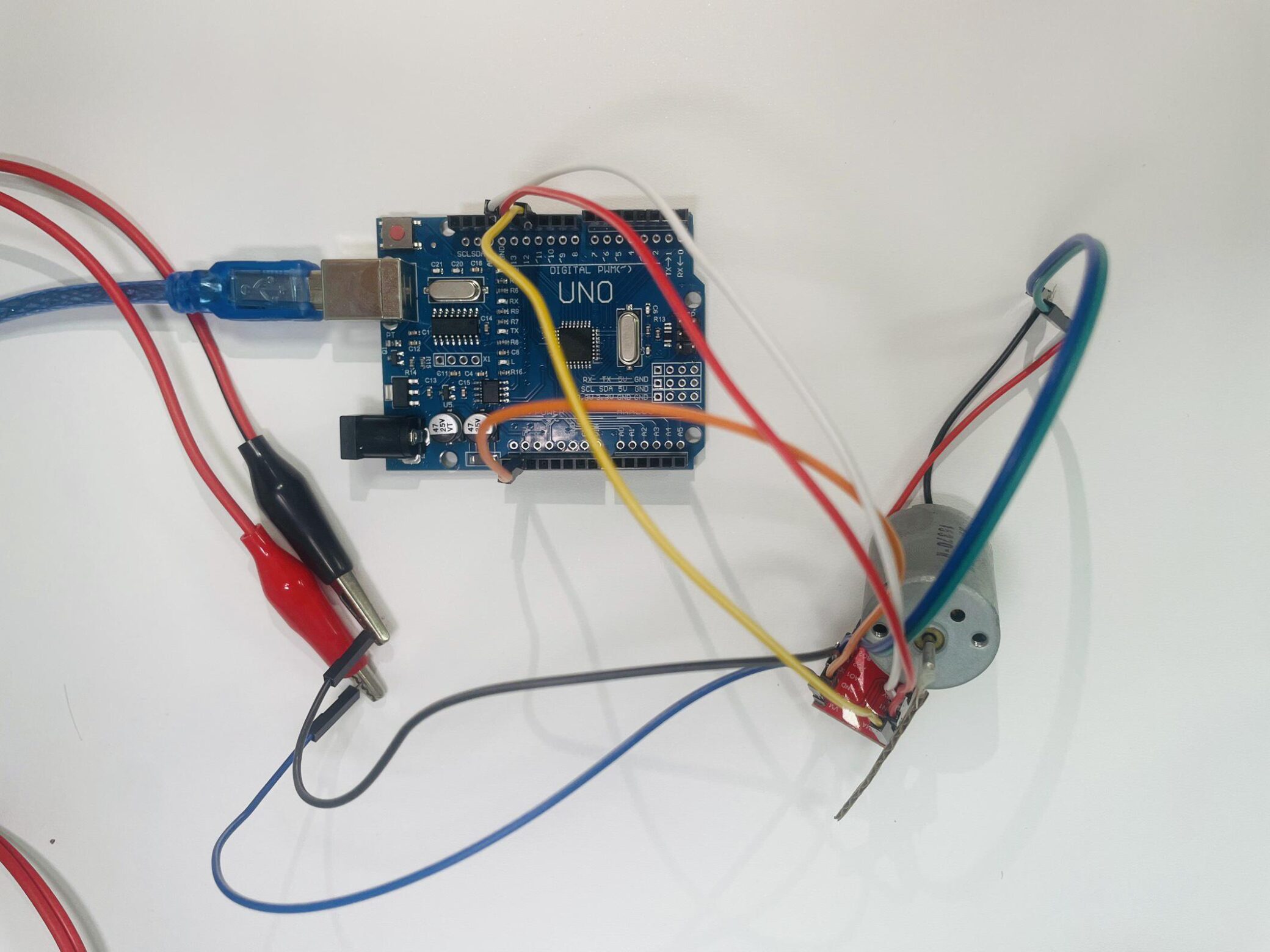
Physical Wiring Diagram

- The VM is connected to the positive pole of the external power supply. GND is connected to the negative pole of the external power supply voltage. VCC is connected to the 5V pin on the Arduino.
- AO1 and AO2 are respectively connected to the two wires of the motor.
- PWMA is connected to Arduino’s pin 11, AIN2 is connected to Arduino’s pin 12, and AIN1 is connected to Arduino’s pin 13.
- The STBY port is connected to the IO pin 4 on the Arduino. When STBY is set to 0, the motor stops completely. When it is set to 1, the motor can work. After setting STBY to 1, the motor can be controlled for forward and reverse rotation through AIN1 and AIN2.
- The same connection method can be used for additional motor.
TB6612FNG Sample Code
					#define PWMA 11
#define AIN1 13
#define AIN2 12
#define STBY 4

void setup() {
    pinMode(PWMA, OUTPUT);
    pinMode(AIN1, OUTPUT);
    pinMode(AIN2, OUTPUT);
    pinMode(STBY, OUTPUT);
}

void loop() {
    digitalWrite(STBY, HIGH);
    digitalWrite(AIN1, HIGH);
    digitalWrite(AIN2, LOW);
    analogWrite(PWMA, 255);
}
TB6612FNG Video Tutorial
Usage Instructions
- Power Supply Design:
– Ensure that the motor power supply (VM) is separately powered from the logic power supply (VCC).
– High power motors should be equipped with the filter capacitors of sufficient capacity .
– Avoid interference from the motor power supply to the MCU power supply.
- Heat Dissipation Considerations:
– Long-term operation under high current requires consideration of cooling measures.
– Add cooling fin if necessary.
Application Scenarios
TB6612 is a high performance and compact motor driver module. Combined with Arduino’s powerful processing capabilities, it is highly suitable for various projects that require motor control, such as intelligent cars, robots, and automated equipment.
In practical applications, it is recommended to optimize and expand the code according to specific requirements, and pay attention to engineering details such as power supply design and heat dissipation treatment to ensure the stability and reliability of the system.
TB6612FNG motor driver Purchase Link
Relative Information
FAQ
- Why isn’t the motor rotating?
If your motor doesn’t rotate, you need to check whether the STBY pin is at a high level, confirm if the PWM signal is being output normally, measure if the voltage at both ends of the motor is normal, and check if the power supply is providing sufficient current. If none of these checks are problematic but the motor still doesn’t rotate, it might be that the module is broken.
- Why can a motor only rotate in one direction?
You need to verify whether the logic of the direction control pins AO1 and AO2 is correct, and confirm that the H-bridge is not damaged (this can be tested by swapping the motor wires).
- What are the reasons for the unstable rotation of the motor?
Perhaps it is due to unstable power supply. In such cases, increase the filter capacitors. Check if the mechanical connections are secure. You can also increase the PWM frequency (for some motors, they are sensitive to low frequency PWM) to make the motor rotation more stable.
- How to solve the problem of severe module overheating?
Ensure good heat dissipation conditions, reduce the PWM duty ratio or decrease the load. Check if the motor current exceeds the rated value. Within the rated voltage range, the chip will not generate much heat.
- Can it drive a 12V/2A motor?
No. The TB6612FNG motor driver chip can drive a 12V motor. However, if the current requirement of your 12V motor exceeds 1.2A, then the TB6612FNG might not be able to meet the demand. The maximum current of the TB6612FNG single channel is 1.2A (peak 3.2A), and exceeding the threshold will cause the chip to be damaged. You need to consider other driving solutions, such as using parallel channels or replacing with a higher current driver chip.
- How to know what motor driver to use?
Selecting the appropriate motor driver requires comprehensive consideration of various factors. It is necessary to conduct in-depth analysis of the motor type, load characteristics, control requirements, and make a choice based on the actual application scenario. For different application scenarios, different driving solutions may be required. For some complex applications, professional assistance may be needed.
- What is a H-bridge?
A H-bridge is an electronic circuit that switches the polarity of a voltage applied to a load.
