What is flame sensor
A flame sensor is an electronic device that can detect flames (or high-temperature heat sources) in the environment and convert them into electrical signals. It’s widely used in fire early warning, safety protection, industrial control, and other fields. Its core function is to quickly determine whether a flame exists by identifying the unique physical characteristics of flames (such as light of specific wavelengths, temperature changes, etc.), and then trigger an alarm or link with other equipment (like fire-extinguishing devices, power-off systems, etc.).
Schematic
Working principle
The combustion process of a flame releases specific forms of energy, and flame sensors detect flames by capturing these characteristics. The common detection principles are as follows.
Optical detection (most commonly used)
Flames emit light of specific wavelengths when burning (mainly infrared and ultraviolet light), and the flame spectra of different combustibles vary.
Infrared flame sensors: Detect infrared radiation emitted by flames. They use optical filters to filter out interference from other light sources in the environment and only respond to specific infrared signals from flames.
Ultraviolet flame sensors: Detect ultraviolet radiation generated during flame combustion. This kind of radiation is rare in ordinary ambient light, so they have strong anti-interference ability and are suitable for outdoor or complex light environments.
Temperature detection
Some sensors are combined with temperature sensors to help determine the existence of flames by detecting a sharp rise in ambient temperature. However, relying solely on temperature detection results in slow response speed, so it’s usually used in combination with optical detection.
Pinout
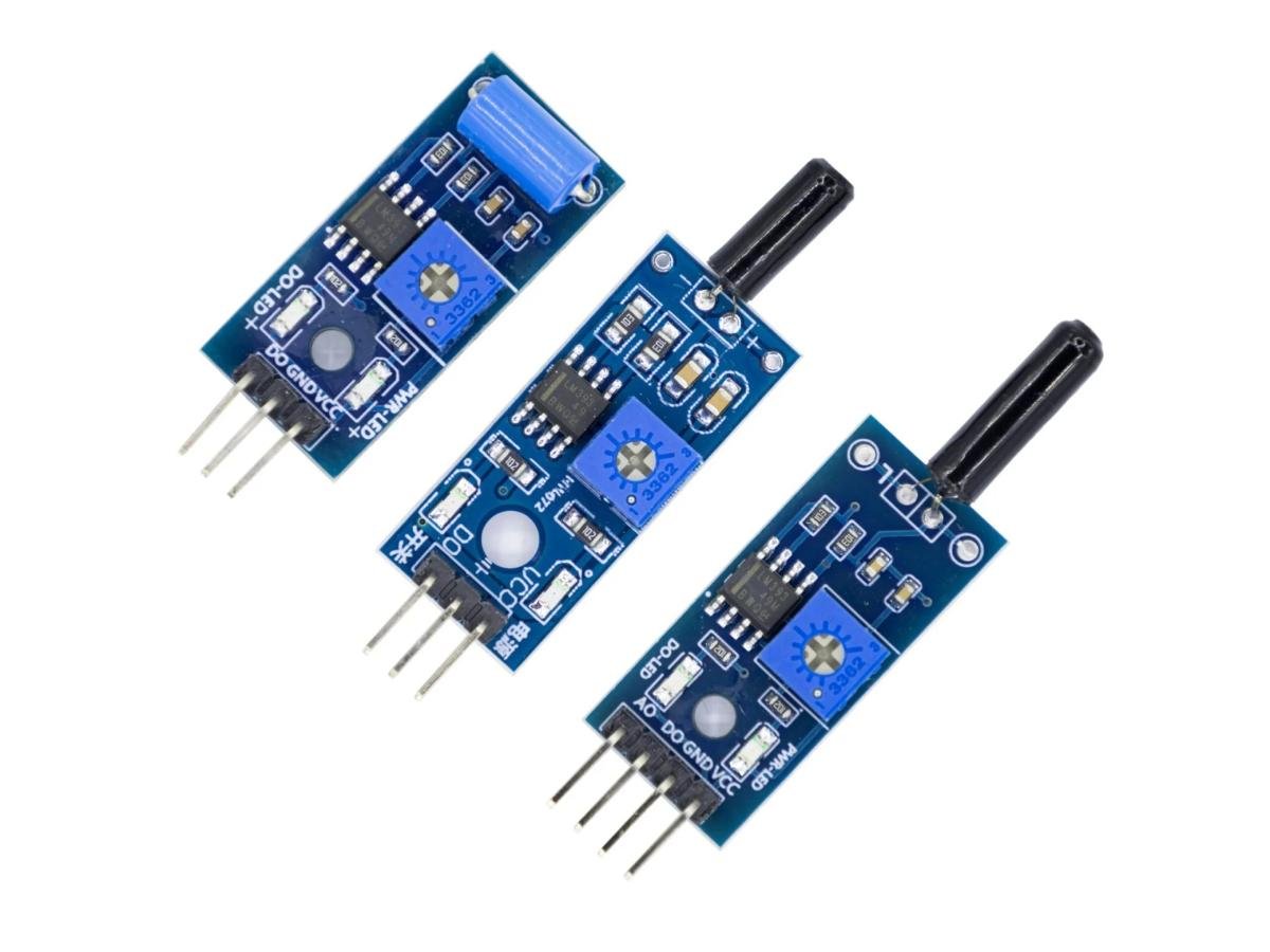
VCC: Positive power output. Connect it to a 3.3V to 5V power supply.
GND: Zero potential reference point. It forms a current loop with VCC, so connect it to the power supply’s GND or negative pole.
DOUT: Digital output. It compares the sensor’s reading with the set threshold and then outputs a high or low level to the control system.
AOUT: Analog output. It directly sends the sensor’s original voltage signal to the control system.
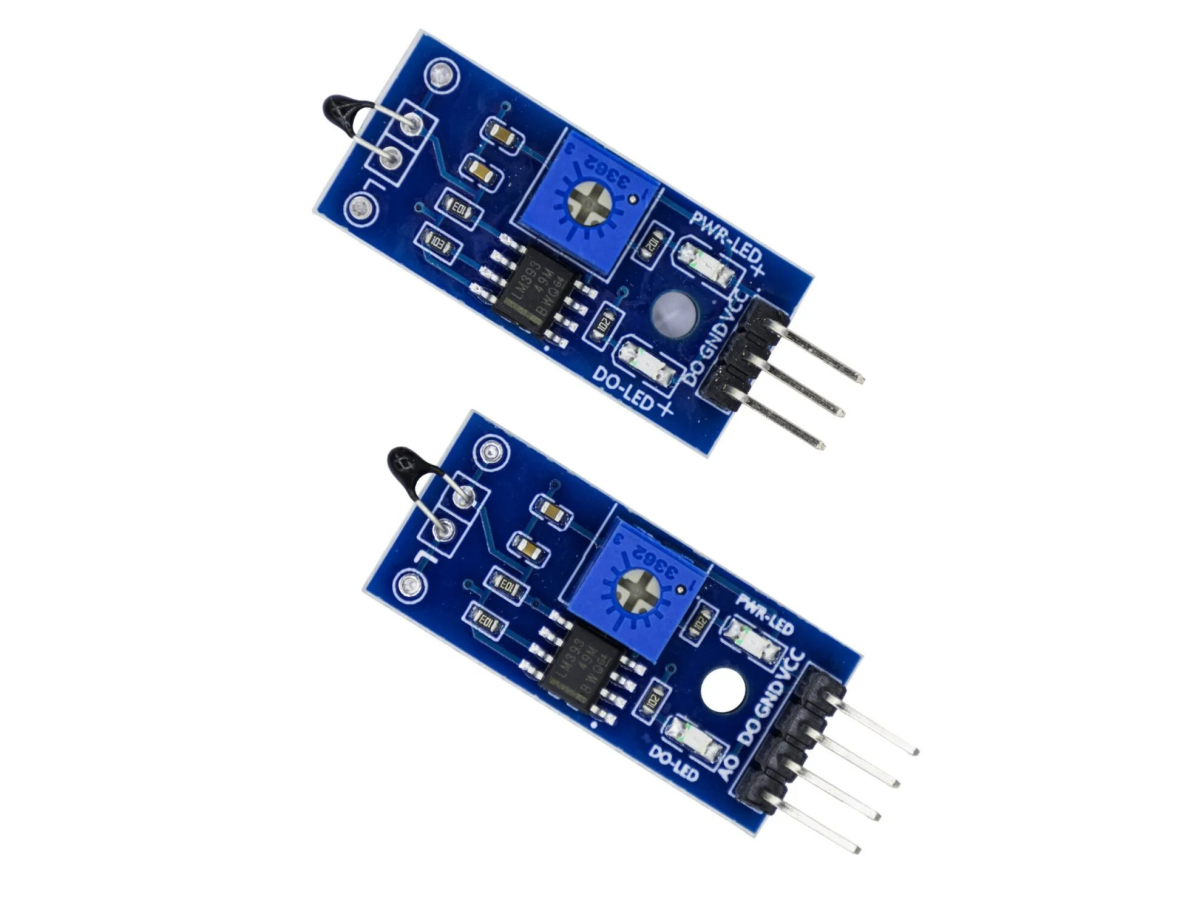
Component
- Sensitive components: Such as infrared receiving tubes and ultraviolet phototubes, which are responsible for capturing light signals from flames.
- Filter circuit: Filters out interference signals from non-flame light sources to improve detection accuracy.
- Amplifying circuit: Converts weak light signals into recognizable electrical signals (analog or digital).
- Output interface: Transmits processed signals (such as high/low levels, voltage changes) to control devices like single-chip microcomputers.
Three-channel flame sensor
The three-channel flame sensor uses three infrared sensors sensitive to infrared rays, each detecting the infrared radiation wavelength of fire within a specific range. Through a programmable algorithm, it checks the proportion and mutual relationship of the data received by the three sensors to reduce false alarms. This design is based on preventing false alarms and improving the sensitivity of infrared flame detectors. At the same time, each signal channel uses multi-frequency infrared technology and automatic digital scaling technology to further optimize detection performance.
Four-channel flame sensor
The four-channel flame sensor has various technical implementations. Some use three infrared sensors and one ultraviolet sensor, combining the characteristics of flames in the ultraviolet and infrared spectra to improve detection response speed. By utilizing the unique performance of flames in different spectral bands, more accurate flame recognition is achieved. Others use four infrared sensors to achieve more precise flame recognition and background noise suppression.
Five-channel flame sensor
Five-channel flame sensors usually use multi-channel infrared detectors and infrared detection technology to detect infrared radiation signals generated during flame combustion. When a flame burns, the infrared radiation signals it produces are received by the sensor and converted into electrical signals, which are then analyzed and processed by a signal processing circuit, and finally, flame signals are output. The five-channel flame sensor module consists of 5 flame detectors arranged at 30-degree intervals, covering a detection range of more than 120 degrees. This module can output analog signals for high-precision measurement, reflecting information such as flame intensity, and can also output digital signals for easy connection with microcomputers and other devices. The sensitivity of the digital output can be adjusted through the on-board potentiometer.
Five-channel flame sensors are suitable for scenarios that require large-area flame detection. For example, in large warehouses, factories, and other large spaces, their detection range of more than 120 degrees can effectively cover larger areas and promptly detect possible flames in all directions. They also play an important role in robot applications that require all-round flame detection, helping robots more comprehensively sense flames in the surrounding environment to make corresponding decisions.
Flame sensor Arduino
Library
This is the Library Manager interface in the Arduino development environment, used to search for and install Arduino libraries
MFRC522: An Arduino RFID library used to read and write RFID cards or tags through the SPI interface.
MFRC522-spi-i2c-uart-async: An Arduino RFID library that supports SPI, I2C, and UART interfaces and has asynchronous callback functions.
MFRC522_fix: Modified based on the original library, it’s an Arduino RFID library used to read and write RFID cards or tags through the SPI interface.
Code