Still having trouble using the MCP2515 CAN bus module and the TJA1050 receiver? Don’t worry! After reading this article, you will have a completely new understanding of this module! Whether you are an electronic novice or an embedded enthusiast, you can easily understand and quickly get started. Get your development board ready, and let’s go together!
What is MCP2515 CAN Bus Module TJA1050 Receiver?
This module is a CAN bus module based on the MCP2515 CAN controller and the TJA1050 CAN transceiver. The circuit design of this module is ingenious and reasonable. The circuit board is exquisite and elegant. The microcontroller program is simple and easy to understand. The module is powered by a 5V DC power supply and can be easily used on traditional 51 single-chip microcontrollers, new 51 single-chip microcontrollers, Arduino, ARM and other controllers through the SPI protocol.
This module communicates with the MCU via the SPI interface. The RPi 2B/3B expansion board contains SPI bus signals, which makes it very convenient to operate this module. This enables us to conveniently obtain the communication data on the CAN bus using the can-util tool, and also allows us to perform read and write operations on the devices on the CAN bus.
Its greatest advantage is that it can communicate with the microcontroller via the SPI interface, without the need for complex timing control. It is highly suitable for single-chip microcontroller platforms with limited resources, such as the 51 series. Moreover, it has built-in 6 mailboxes, allowing for flexible configuration of sending and receiving buffers. It also has strong anti-interference capabilities and is suitable for communication in complex electromagnetic environments.
When paired with the TJA1050 CAN transceiver, it can easily achieve communication at the physical layer of the CAN bus! It can be said that the combination of MCP2515 and TJA1050 is the perfect golden pair for getting started with CAN communication!
Working Principle
- MCP2515 CAN Bus Module Schematic Diagram
The MCP2515 supports the highest 10 MHz SPI communication, which can be directly connected to the SPI peripheral on the microcontroller and supports mode 0 and mode 3. When performing any operation, the CS pin must be pulled low. At the same time, it should be noted that before transmitting another instruction, the chip select should be set high first and then pulled low.
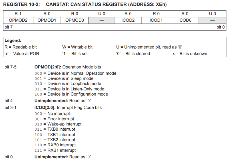
The MCP2515 has 5 working modes. The desired mode can be set through the CANCTRL register’s REQOP. It should be noted that the mode will only be actually changed after all suspended message transmissions are completed. The current mode can be read through the CANSTAT register’s OPMODE. It is recommended to read the CANSTAT register again after changing the mode to ensure successful writing and entering the desired mode.
1) Configuration mode: The chip must be initialized before activation. Power-on, using the RESET pin, or changing the REQOP<2.0> in the CANCTRL register can all enter the configuration mode. The following registers can only be modified in the configuration mode.
Label | Name | Function |
1 | CNF1, CNF2, CNF3 | Baud rate configuration |
2 | TXRTSCTRL | Send pin configuration |
3 | Filter registers | Filter configuration |
4 | Mask registers | Mask configuration |
2) Sleep Mode: The MCP2515 has an internal sleep mode, which is used to minimize the current consumption of the device. Even when the MCP2515 is in sleep mode, the SPI interface remains active for reading purposes. The sleep mode can be entered by modifying the CANCTRL register. After writing to the register, a read operation should be performed to ensure that the chip enters the sleep mode.
>> Sleep Wakeup: In sleep mode, it can be awakened via the CAN bus or switched to a different mode through SPI. Typically, CAN bus wake-up is a common usage. The CANINTE register needs to be configured to enable the wake-up interrupt. When the level on the RXCAN pin changes, the messages that wake up from the sleep mode and the messages received during the wake-up process will be ignored. At the same time, the chip is awakened, and the INT pin can capture the falling edge transition. The MCP2515 will automatically enter the listen-only mode. At this point, the chip should be manually set to the normal mode.
3) Listen-only mode: The listen-only mode enables the MCP2515 to receive all messages, including error messages. This mode can be used for bus monitoring applications or for detecting baud rates during hot-plugging situations.
4) Loopback Mode: The loopback mode enables the spontaneous transmission and reception of messages between the transmit buffer and the receive buffer within the device, without the need to use the CAN bus. This mode can be utilized for system development and testing.
5) Normal Mode: This mode is the standard operation mode of MCP2515. When the device is in this mode, it will actively monitor all messages on the bus and generate acknowledgment bits and error frames, etc. Only in the normal mode can MCP2515 transmit messages on the CAN bus.
1) Reset instruction: Resets the registers to their initial state, causing the chip to enter the configuration mode. It is recommended to execute this instruction as the first step in the initialization process.
2) Read Instruction: After pulling the CS pin low, send the read instruction and 8-bit address code to MCP2515 one by one. MCP2515 will transfer the data in the specified address register through the SO pin. After each data byte is transferred out, the internal address pointer of the device will automatically increase by one to point to the next address. Therefore, by continuously providing clock pulses, the read operation can be performed on the next consecutive address register. By using this method, data from any consecutive address registers can be sequentially read. By raising the level of the CS pin, the read operation can be ended.
3) Read Receive Buffer Instruction: A common instruction for reading received information. Compared with the read instruction, it omits one byte of address bit and automatically clears the receive flag (CANINTF.RXnIF) after the CS pin is pulled high. There is no need to manually execute the clear instruction. It is strongly recommended to use this instruction when reading the data in the receive buffer.
4) Write Instruction: After pulling the CS pin low, send the write command, address code, and at least one byte of data to the MCP2515 (if there are multiple data, their addresses are consecutive) in sequence.
5) Load Transmit Buffer Instruction: Similar to reading the receive buffer, this command also omits one byte of the address bit. It enables faster writing of the flag ID, extension ID, DLC and data frame of the transmission frame. It is strongly recommended to use this command to load the transmission frame.
6) Request to Send Instruction: By using the RTS command, one or more transmit buffer can be initiated to send messages. The bit3-bit0 of this command indicate which transmit buffers are enabled for sending. This command will set the TxBnCTRL.TXREQ bit to 1 for the corresponding buffer. If the sent RTS command has nnn = 000, this command will be ignored.
7) Bit Operation Instruction: This instruction enables the setting of “1” or clearing of the specified bits in the register. After the chip selection is lowered, send the bit operation instructions, register addresses, masks and data codes in this way. The mask bit with “1” allows for changes, while “0” prohibits changes. For the bits that are allowed to be changed, the data code represents the target code that the register will be modified to.
For example:
Note: Not all registers support bit operation instructions. Only the grayed-out registers can perform bit operations.
8) Read Status Instruction: The read status instruction enables a single instruction to access the commonly used status bits for message reception and transmission.
9) RX Status Instruction: The RX Status instructionis used to quickly determine the filters that match the message and message type (standard frame, extended frame, or remote frame). After the command bytes are sent, the controller will return an 8-bit data packet containing the status information.
The MCP2515 follows the error detection mechanism of the CAN protocol. The following will elaborate on each aspect separately:
(1) CRC error: Using cyclic redundancy check (CRC), the transmitter calculates a special check bit for the bit sequence from the start of the slave frame to the end of the data field. This CRC sequence is transmitted in the CRC field, and the receiving node also uses the same formula to calculate the CRC sequence and compares it with the received sequence. If a mismatch is detected, a CRC error occurs and an error frame is generated, and the transmission is repeated.
(2) ACK response error: In the ACK field of the message, the sender checks whether there is an explicit bit. If not, it is considered that no other nodes have correctly received this frame. A confirmation error has occurred, an error frame will be generated, and the transmission will be repeated.
3) Format Error: If the node detects the dominant bit in one of the four segments, including the frame end, inter-frame space, confirmation delimiter, or CRC delimiter, a format error occurs and an error frame is generated, and the transmission is repeated.
4) Bit Error: If the transmitter detects a bit level that is opposite to the one it is sending (that is, sending an active level and detecting a passive level, or sending a passive level and detecting an active level), a bit error occurs.
>> Exceptional case: In the arbitration field and confirmation slot, if the sender sends an implicit bit and the receiver detects an explicit bit, no error will occur because normal arbitration is in progress.
5) Bit stuffing error: If six consecutive bits of the same polarity are detected between the frame start and the CRC delimiter, the bit stuffing rule is violated. A stuffing error occurs and an error frame is generated, and the frame is retransmitted.
The detected errors are notified to all other nodes through error frames. The transmission of error messages is terminated and the message frames are repeated as soon as possible. Based on the value of the internal error counter, the MCP2515 contains two error counters: the receive error counter (REC) and the transmit error counter (TEC), which increment/decrement according to the CAN bus specification. Each CAN node is in one of the three error states:
- Error-active: The node can transmit messages and active error frames (composed of leading bits) in their normal state without any restrictions.
If both error counters are below 128, the MCP2515 is in Error-active mode.
- Error-passive: Messages can be transmitted and passive error frames (composed of trailing bits) can be sent.
If at least one error counter is equal to or greater than 128, it is in Error-passive mode.
- Bus-off (Transmitter): Messages cannot be received or sent.
If the TEC exceeds the 255 bus-off limit, it will enter bus-off mode. The device remains in this state until it receives the bus-off recovery sequence. The bus-off recovery sequence consists of 128 consecutive 11-bit trailing bits.
MCP2515 CAN Bus Module Pin Function
Pin | Function Definition |
VCC | 5V power input pin |
GND | Power ground pin |
CS | SPI SLAVE select pin (low level valid) |
SO | SPI master input and slave output pins |
SI | SPI master output and slave input pins |
SCLK | SPI clock pin |
INT | MCP2515 interrupt pin |
J1 | 120R Selection of resistance terminals |
J2 | CANH、CANL KF301-2P series output |
J3 | CANH、CANL pin header |
Module Feature
- Supports CAN V2.0B technical specification, with a communication rate of 1Mb/s.
- Data field ranging from 0 to 8 bytes.
- Standard frame, extended frame and remote frame.
- Module powered by 5V DC supply, controlled by SPI protocol.
- 120 ohm terminal resistor, the J1 can be short-circuited by using the short-circuit cap.
- Module size: 34.8mm * 22.7mm.
- Working current: typical value 5mA, standby current 1 microampere. Excluding the power indicator light.
- Operating temperature: industrial grade -40℃ to +85℃, extended grade -40℃ to +125℃.
Initial Configuration
① RESET
When the MCP2515 is powered on, it automatically resets. However, the manual suggests performing a reset operation before initialization. There are two methods for resetting: (1) Hardware reset: pull down the RESET pin; (2) Software reset: execute the SPI reset instruction.
After resetting, the CANCTRL and CANSTAT registers were read respectively. When resetting and entering the configuration mode, CANCTRL was 0x87 and CANSTAT was 0x80. The bit definitions of the two registers are as follows:
② Baud rate setting
When CAN is communicating, the baud rate on the bus must be kept consistent. The MCP2515 uses a digital phase-locked loop (DPLL) to divide each bit time into multiple segments composed of the smallest time period. This smallest time period is called the time quantity (TQ). By changing the CNF1, CNF2, and CNF3 registers, the desired baud rate can be achieved. Among them, the Normal Bit Rate is the general bit rate and is referred to as NBR hereinafter.
And the following conditions need to be met:
From the above parameters, it can be known that the crystal oscillator frequency in the circuit is 8 MHz, and the bit time is greater than or equal to 5 TQ. Therefore, the following are the baud rate configuration parameters at 500 kbps: SyncSeg = 1 TQ, PropSeg = 2 TQ, PS1 = 3 TQ, PS2 = 2 TQ, BPR = 0, SJW = 0. The related configuration registers are as follows:
③ Send configuration
In the MCP2515, there are a total of 3 configurable priority transmit buffer (note that the sub-priority is the internal sending priority of the chip, and it should be distinguished from the CAN bus arbitration priority). During initialization, the sending priority, CAN-ID and data frame length DLC of the required buffers should be configured at least. Here is a configuration method.
>> TXRTSCTRL: Enables/Disables the falling edge of the TXnRTS pin to send requests
>> TXBnCTRL: Configures the sending priority of the transmit buffer
>> TXBnDLC: Configures remote frames or data frames and their lengths
>> Use the loading buffer instruction or write the CAN-ID and data frame through the TXBnSIDH, TXBnSIDL, TXBnEID8, TXBnEID0, TXBnDm registers
>> Flip the TXnRTS pin or use the RTS request sending instruction
Here, n is 0-2 corresponding to 3 transmit buffers, and m0-m7 correspond to 8-byte data frames.
④ Reception Configuration
In the MCP2515, there are two complete receive buffers, RXB0 and RXB1, and an independent message assembly buffer(MAB). After receiving the message, it will first enter MAB. Only after meeting the filter conditions will it be allowed to enter RXB0 or RXB1.
1) Priority and Filters
RXB0 is the receive buffer with a higher priority, featuring a mask and two filters. RXB1 is the receive buffer with a lower priority, having a mask and four filters. To enable the filters of RXB0, the bit RXB0CTRL.BUKT must be set to “1”, at which point filters 0-1 are available for RXB0. In the state where RXB0CTRL.BUKT is “1”, filters 0-5 are available for RXB1, while filters 2-5 are available for RXB1 when RXB0CTRL.BUKT is “0”, and RXB0 has no corresponding filters available for use.
For the RXBnCTRL register, the RXM <1:0> bits can be set to select whether the CAN-ID received by the buffer is allowed to pass through both standard IDs and extended IDs. Combined with masks and filters, more detailed filtering can be performed. The truth table of the mask and filter is as follows:
Mask Bit | Filter Position | Message ID Bit | Accept or Reject this bit |
0 | X | X | Receive |
1 | 0 | 0 | Receive |
1 | 0 | 1 | Reject |
1 | 1 | 0 | Reject |
1 | 1 | 1 | Receive |
2) Receive Flag
When a message is moved to any receive buffer, the corresponding CANINTF.RXnIF bit is set to “1”. To allow new messages to be received into the buffer, this bit must be manually cleared by the program. This bit provides a forward lock to ensure that our microcontroller has completed message processing before the MCP2515 attempts to load a new message into the receive buffer.
If the CANINTE.RXnIE bit is set to “1”, an interrupt will be generated on the INT pin to indicate that a valid message has been received. Furthermore, if the receive buffer is configured with full pins, the corresponding RXnBF pins will generate a low level. In this case, the microcontroller can set the GPIO connected to the RXnBF pin as an external interrupt triggered by the falling edge. After receiving the message, the data frame will be transferred to the FIFO, and then the flag CANINTF.RXnIF will be cleared.
3) Configuration Example
To sum up, in actual engineering, the receive buffer RXB0 should have a filtering function. Here is the configuration method:
>> BFPCTRL: The received information can be obtained through the falling edge of the RXnBF pin.
>> The standard ID and extended ID that meet the filtering criteria can be accepted. When BUKT is set to “1”, it allows RXB0 to use filters 0-1.
>> Configuration mask-related registers RXMnSIDH, RXMnSIDL, RXMnEID8, RXMnEID0
Here, n0-n1 correspond to the masks of the two receiving buffers respectively, and they are one-to-one corresponding.
>> Configuration filter-related registers RXFnSIDH, RXFnSIDL, RXFnEID8, RXFnEID0
Here, n0-n5 correspond to the 6 filters.
⑤ Interrupt Configuration
The MCP2515 has eight interrupt sources. The eight interrupt sources are 3 transmission interrupts, 2 reception interrupts, 1 message error interrupt, 1 bus activity interrupt, and 1 error interrupt. The CANINTE register contains the interrupt enable bits for enabling each interrupt source. The CANINTF register contains the interrupt flags for each interrupt source. When an interrupt occurs, the INT pin will be pulled low by the MCP2515 and remain in a low state until the MCU clears the interrupt.
Note: Interrupts will only be cleared after the conditions that caused the corresponding interrupt disappear.
During the working mode, the sleep mode and bus wake-up have been mentioned,it is necessary to initialize CANINTE.WAKIE as 1. After enabling the receive interrupt, it can replace the RX0BF and RX1BF pins, saving two I/O resources. At the same time, to provide real-time feedback on the error conditions on the CAN bus, the error interrupt needs to be enabled. In actual use, the INT pin can be configured as an external interrupt. After triggering, read the CANINTF register to query the current interrupt source and then proceed with further processing. The configuration is as follows:
>> CANINTE: Enable interrupt
>> CANINTF: Clear interrupt flag
Relative Information
Purchase Link
FAQ
1、 What protocol is MCP2515?
The MCP2515 CAN Bus Controller is a simple Module that supports CAN Protocol version 2.0B and can be used for communication at 1Mbps. In order to setup a complete communication system, you will need two CAN Bus Module.
2、 Does a CAN bus need a ground?
CAN buses are galvanically isolated, so a CAN GND wire must be connected between the devices. If some device in the bus doesn’t have a separate CAN GND connection (for example a PLC without an isolated CAN interface), use the common 24 V ground connection.
3、How to test a CAN bus module?
Measure voltage on any of disconnected plugs between CAN HI and GROUND. The resulting voltage should be between 2.5 and 3.0VDC. At the same location, measure voltage between CAN LOW and GROUND. The resulting voltage should be between 2.5 and 2.0 VDC.