Vibration sensors are the silent guardians of the mechanical world! Among the types of vibration sensors, piezoelectric sensors act as sensitive “nerve endings” while MEMS sensors work like microscopic “dance critics”. For earth-shaking events, the mighty seismic vibration sensor stands guard like a sentinel. Meanwhile, the vibration detection sensor plays mechanic, listening intently to machines’ whispers before they become screams.
When it comes to the detection and sensing of object vibrations, the vibration module becomes a common and practical tool. This compact and powerful device can be used in various applications, ranging from smart homes to security systems, and even in industrial automation fields. By sensing and converting object vibrations into electrical signals, the vibration module plays an important role in many aspects.
This article will introduce the principle, working mode and applications of the vibration modules in the SW series across various fields. Whether you are interested in electronic technology or wish to learn how to use the vibration modules to improve products or systems, this article will provide you with valuable information and insights.
What is vibration sensor?
Vibration sensors, also known as vibration transducers or accelerometers, are devices designed to detect and measure vibrations in various mechanical systems. These sensors play a crucial role in monitoring the health and performance of machinery, structures, and equipment.
The core principle of vibration sensors is to convert mechanical motion into electrical signals, and then analyze and interpret these signals. They typically consist of a sensing element, such as a piezoelectric crystal or a micro-electromechanical system (MEMS), which generates an electrical signal proportional to the applied force when subjected to mechanical vibration.
These sensors can detect a wide range of vibration frequencies, from low-frequency oscillations to high-frequency vibrations. They can measure various parameters, including amplitude, frequency, and acceleration, providing valuable insights into the condition and behavior of the monitored system.
Vibration sensors are widely used in industries such as manufacturing, automotive, aerospace, and construction. They help with predictive maintenance, fault diagnosis, and performance optimization. By continuously monitoring vibration levels, these sensors can detect potential problems early, preventing costly downtime and maintenance costs.
Vibration Sensor Working Principle
(1)SW-18010P Working Principle
- When there is no vibration or the vibration intensity does not reach the set threshold, the DO port outputs a high level. When the external vibration intensity exceeds the set threshold, the module D0 outputs a low level.
- The digital output D0 can be directly connected to the microcontroller. Through the microcontroller, the high and low levels can be detected, thereby detecting the vibration of the environment.
(2)SW-18015P Working Principle
When SW-18015P is stationary, it is in an open circuit (OFF) state. When it is touched by an external force and reaches the corresponding vibration force, or when the moving speed reaches an appropriate eccentric force, the conductive pins will instantaneously conduct and enter a momentary ON state. When the external force disappears, the switch returns to the open circuit (OFF) state.
Therefore, when there is no vibration or the vibration intensity does not reach the set threshold, the DO port outputs a high level. When the external vibration intensity exceeds the set threshold, the module D0 outputs a low level.
Please note that this module triggers very quickly when sensing small vibrations and cannot drive relays. Some materials indicate that it can be directly connected to the relay module, but the actual application effect is not good.
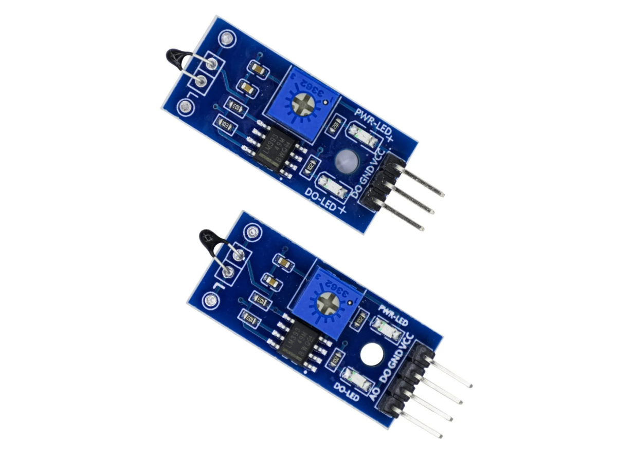
(3)SW-420 Working Principle
When there is no vibration, the vibration shaft is stationary, and the guide pins A and B are in a conductive state. Normally, any angle switch is in an on state. When subjected to vibration or movement, the vibration shaft will move or vibrate, causing the guide pins A and B to disconnect.
The characteristic of this switch is that it is generally in a conductive state normally, but it will briefly disconnect when vibrating or moving. Therefore, its sensitivity is very high. At the same time, when there is no vibration, the circuit is conductive, so it is a normally-closed vibration sensor.
(Here is the principle of the sensor, not the module.)
Here, an LM393 voltage comparator is used. (When the LM393 has no negative feedback) When the voltage at the positive input terminal is higher than that at the negative input terminal, the output is a high level, which is VCC. When the voltage at the negative input terminal is higher than that at the positive input terminal, the output is a low level, which is 0V. Therefore, the output of the LM393 is a digital signal of 0 or 1. Because the sensor is normally-closed, when there is no vibration, the voltage at the inverting input terminal of the LM393 is higher than that at the positive input terminal, and at this time, the output is a low level. When there is vibration, the sensor disconnects, and the voltage at the positive input terminal is higher than that at the inverting input terminal, at this time, the output is a high level.
Pin Functions
Vibration Sensor Pin Diagram
| Pin |
Definition |
| VCC |
External connection to 3.3V – 5V (can be directly connected to 5V microcontroller and 3.3V microcontroller) |
| GND |
Grounding |
| DO |
Small board digital output interface (0 and 1) |
| AO (SW-18010P) |
Simulation output, invalid, not connected |
Vibration Sensor Arduino
SW-18010P Arduino
VCC ——> 5V D0 ——> D2
GND ——> GND LED ——> D3
- SW-18010P Effect Demonstration
SW-18015P Arduino
VCC ——> 5V D0 ——> D2
GND ——> GND LED ——> D3
- SW-18015P Effect Demonstration
SW-420 Arduino
VCC ——> 5V D0 ——> D2
GND ——> GND LED ——> D3
- SW-420 Effect Demonstration
Usage Instructions
① Connect the VCC and GND properly, and the module power indicator light will turn on.
② Place the module horizontally on the desktop, slowly rotate the module upwards, the switch indicator light will turn on, then rotate the module in the opposite direction, back to the original state, and the switch indicator light will turn off. This phenomenon indicates that changing the sensor angle can trigger the module, thereby causing the switch indicator light to turn on.
③ When the module is not tilted or the tilt angle does not reach the set threshold, the D0 port outputs a high level. When the sensor tilt angle exceeds the set threshold, the module D0 outputs a low level.
④ The digital output D0 of the small board can be directly connected to the microcontroller. Through the microcontroller to detect the high and low levels, thereby detecting the change in the object’s angle.
① Connect the VCC and GND, and the power indicator light of the module will turn on.
② Place the module gently on the table, adjust the blue potentiometer on the board until the switch indicator light on the board lights up. Then slightly adjust the potentiometer to turn off the switch indicator light. Then tap the tabletop to make the vibration sensor feel the vibration. At this time, the switch indicator light will again turn on. When the vibration stops, the switch indicator light will also turn off. This phenomenon indicates that vibration can trigger the module, thereby turn on the switch indicator light.
① Connect the VCC and GND, and the module’s power indicator light will turn on.
② When the power supply is normal, both the two LED lights are on, and the DO pin outputs a low level. When the sensor is tapped, the DO-LED light goes off, and the DO pin outputs a high level.
Note: The vibration sensor has a very high sensitivity. After tapping the sensor once, DO immediately outputs a high level, and then it becomes a low level. Therefore, if you need to continuously output a high level, you need to tap the sensor continuously.
③ Additionally, there is a sensitivity adjustment potentiometer on the sensor. You can use the cross-shaped knob to adjust the sensitivity. If only the PWR-LED light is on after power-on, it indicates that the highest sensitivity has been reached. You need to rotate the adjustment to make both lights on. Sometimes even after continuous tapping of the sensor, the DO-LED does not go out, indicating that the lowest sensitivity has been reached. You need to rotate the adjustment to make the DO-LED go out when tapping.
Vibration Sensor Application Scenarios
Vibration sensors are widely used in various industries and applications due to their ability to monitor and analyze mechanical vibrations. Here are some common applications:
- Predictive Maintenance: Vibration sensors play a crucial role in predictive maintenance programs, by continuously monitoring the health and performance of machinery and equipment. By detecting changes in vibration levels, these sensors can identify potential faults before they escalate into costly failures, allowing for timely maintenance and repair.
- Condition Monitoring: In manufacturing plants and industrial facilities, vibration sensors are used for condition monitoring of rotating machinery such as motors, pumps, and turbines. By monitoring the vibration levels, these sensors can detect abnormal conditions such as imbalance, misalignment, and bearing wear, allowing for early intervention to prevent downtime and production losses.
- Structural Health Monitoring: Vibration sensors are used in structural health monitoring (SHM) systems to assess the integrity and safety of buildings, bridges, dams, and other civil infrastructure. These sensors monitor vibrations caused by environmental factors, traffic loads, and seismic events, providing valuable data for evaluating structural health and identifying potential structural defects or damages.
- Vehicle Health Monitoring: In the automotive and aerospace industries, vibration sensors are used to monitor the health and performance of vehicles and aircraft. They are applied in engine and transmission monitoring systems to detect abnormal vibrations caused by mechanical failures or component wear. Additionally, vibration sensors are also used in flight data recorders (black boxes) to capture and analyze the vibrations of aircraft during flight.
- Earthquake and vibration monitoring: Vibration sensors, such as accelerometers and seismometers, are widely used in earthquake and vibration monitoring networks to detect and record ground vibrations caused by seismic events. These sensors assist seismologists and geologists in studying seismic activities, assessing seismic risks, and developing early warning systems to mitigate the impact of earthquakes on humans and infrastructure.
- Piezoelectric sensor: The piezoelectric sensor utilizes the piezoelectric effect to generate electrical signals under the influence of mechanical stress or vibration. It has extremely high sensitivity and is suitable for detecting high-frequency vibrations. Therefore, it is highly suitable for applications such as structural health monitoring and machine condition monitoring.
Vibration Sensor Purchase Link
FAQ
What factors can affect the accuracy of vibration measurement?
Several factors can influence the accuracy of vibration measurement, including the placement of the sensor, the installation method, environmental conditions, and sensor calibration. Carefully considering these factors is crucial for ensuring accurate and reliable vibration monitoring.
How to test the vibration sensor?
Perform a static test to verify the zero-gravity bias and sensitivity of the sensor. Place the sensor at a stable and known reference position. Measure the output signal and compare it with the expected value. This test ensures that the sensor can accurately detect static or low-frequency vibrations.