Precision capture of every degree of tilt! This sensor redefines “attitude sensing.”
Table of Contents
Recently, tilt sensors have remained a hot topic. Today, we’ll dive deep into the world of tilt sensors.
What is a tilt sensor module?
A tilt sensor is a device that can detect the tilt state of an object. It usually consists of a sensing element, a conversion element, and a signal processing circuit. The sensing element can detect changes in the object’s tilt angle and convert these changes into measurable physical quantities. The conversion element then transforms the physical quantities output by the sensing element into electrical signals. The signal processing circuit further processes the electrical signals (such as amplification and filtering) and finally outputs information that accurately reflects the object’s tilt state. Currently, tilt sensors are widely used in many fields such as industrial automation, aerospace, automotive electronics, and consumer electronics, providing important safety guarantees for the stable operation and safety monitoring of equipment.

How does tilt sensor module work?
The working principle of a tilt sensor is that it measures the tilt angle by detecting changes in the object’s direction relative to gravity.
When an object tilts, its angle relative to the direction of gravity changes. The sensing element inside the tilt sensor can sensitively capture this angle change and convert it into corresponding physical signals, such as changes in resistance value, capacitance value, or voltage. Subsequently, the conversion element accurately converts these physical signals into electrical signals. After the electrical signals undergo a series of processing (such as amplification and filtering) by the signal processing circuit, numerical information that accurately reflects the tilt angle and direction of the object can be obtained. This allows the device to make corresponding adjustments or issue early warnings based on this information.
Types of tilt sensor modules
Common types of tilt sensor modules include capacitive tilt sensors, resistive tilt sensors, and liquid-level tilt sensors. Capacitive tilt sensors measure the tilt angles by utilizing the characteristic that capacitance value changes with the tilt angle. Resistive tilt sensors reflect the tilt state of an object through changes in resistance value. Liquid-level tilt sensors realize tilt detection by converting the change in the position of the liquid surface when tilted into an electrical signal. Different types of tilt sensors have their own characteristics and applicable scenarios, and you can choose according to your specific needs.
What is a tilt sensor used for?
Tilt sensors are often used in many scenarios. In the field of industrial automation, they can be used to monitor the tilt state of large mechanical equipment. When the tilt angle of the equipment exceeds the safe range, an alarm is issued in a timely manner to prevent the equipment from being damaged or safety accidents from occurring due to excessive tilt, thereby ensuring the stable progress of the production process. In the aerospace field, tilt sensors can accurately measure the tilt angle of aircraft, provide pilots with accurate data, assist them in adjusting the flight attitude, and ensure flight safety.
In the field of automotive electronics, they can be installed in vehicles to monitor the tilt of the vehicle in real time. For example, when the vehicle is at risk of rolling over, safety devices are triggered in a timely manner to protect the lives of the people inside the vehicle. In the field of consumer electronics, tilt sensors are also used in some smart wearable devices and game controllers to bring users a richer interactive experience. For example, tilting the device can realize the character movement or operation control in the game.
What is the composition of the tilt sensor module ?
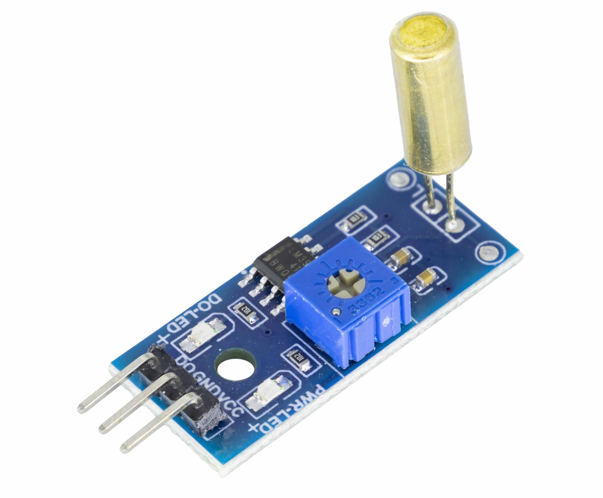
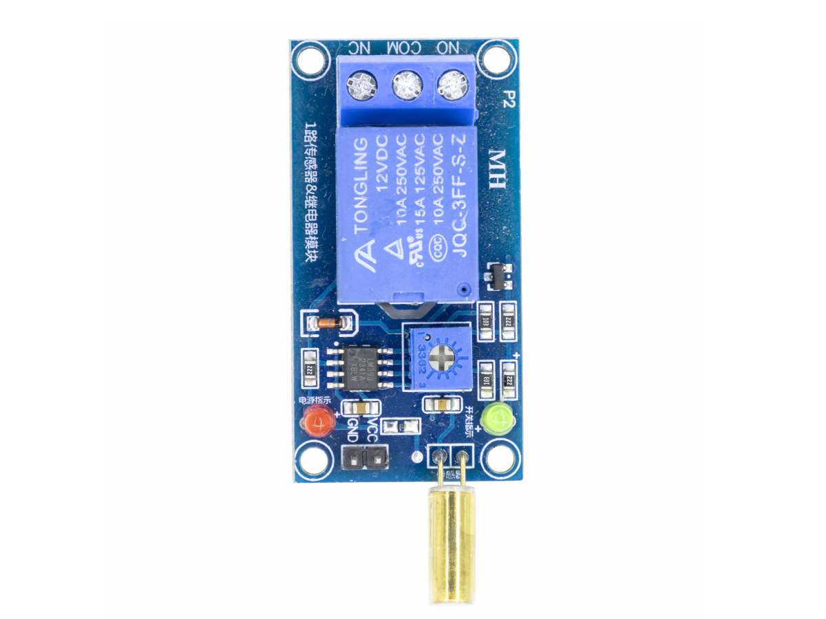
A tilt sensor is mainly composed of the following components:
|
Component |
Function Description |
|
Mechanical tilt switch |
Core component;a sealed cylinder/tank contains a conductive ball (or mercury). When tilted, the ball rolls to bridge the contacts and close the circuit; it opens when reset. |
|
Comparator chip |
Compares the original signal of the tilt switch with the reference voltage and outputs a logic level (low level 0V when closed, high level 5V when open). |
|
Sensitivity potentiometer |
Adjusts the reference voltage of the comparator to change the tilt angle required to trigger the output change. |
|
Resistor |
Includes pull-up/pull-down resistors (to ensure stable output when the switch is open) and LED current-limiting resistors. |
|
LED indicator |
The power LED indicates that the module is powered (5V); the status LED lights up when tilt is detected. |
|
PCB and pin header |
The PCB accommodates all components and provides soldering points; the pin header is used to connect to external circuits (e.g., microcontrollers). |
DC 5V Tilt Sensor Module PINS
A DC 5V tilt sensor module is usually equipped with multiple pins for connecting and communicating with external circuits. The following are the main function descriptions of the module’s pins:
- VCC pin: This pin is used to connect a 5V DC power supply to provide a stable working voltage for the entire sensor module, ensuring the normal operation of the module.
- GND pin: Ground pin, used to connect the module’s circuit to the ground wire to form a complete current loop. Proper grounding can ensure the stability and anti-interference ability of the module.
- OUT pin: Output pin, used to output the tilt state information detected by the sensor in the form of electrical signals. When the module detects a tilt, the OUT pin will output a corresponding logic level (such as low level 0V or high level 5V) for external circuits (likemicrocontrollers) to read and process.
In addition to the above basic pins, some DC 5V tilt sensor modules may also be equipped with other functional pins, such as a sensitivity adjustment pin (used to adjust the sensitivity of the module through a potentiometer) and a status indicator pin (used to connect an LED indicator to visually display the working state of the module). The existence of these pins makes the module more flexible and easy to use.
Roduct Parameter Sheet for DC 5V Tilt Sensor Module
|
DC 5V Tilt Sensor Module |
Specifications |
|
Supply Voltage |
12V DC |
|
Operating Current |
More than 100mA |
|
Operating Temperature |
Between 0°C and +80°C |
|
Load |
250V 10A AC or 30V 10A DC |
DC 5V Tilt Sensor DATASHEET
We provide the datasheet of the Tilt Sensor for your reference here.
FAQS
What is the difference between gyroscope and tilt sensor?
|
Characteristic |
Gyroscope |
Tilt Sensor |
|
Measured Quantity |
Angular velocity (rate of rotation: how fast the device is turning). |
Static tilt angle (orientation: how far the device is tilted relative to gravity). |
|
Sensitivity to Motion Type |
Only detects dynamic rotation (changing angular velocity). Cannot measure static tilt (e.g., a gyro won’t know if a phone is lying flat or tilted 45° unless it’s rotating into that position). |
Only detects static orientation (relative to gravity). Cannot measure fast rotation (e.g., a tilt sensor can’t track how quickly a wheel spins). |
|
Accuracy Over Time |
Prone to drift (small measurement errors accumulate over time, even when stationary). For example, a gyro in a drone may slowly miscalculate its orientation after 10 minutes. |
No drift (gravity is a stable reference). Tilt sensors maintain consistent accuracy indefinitely when stationary. |
|
Response Speed |
Very fast (responds to rapid rotation in milliseconds). Ideal for tracking fast motion (e.g., a game controller’s quick twists). |
Slow (optimized for static or slow-moving tilt). Lags if the device tilts too quickly. |
|
Power Consumption |
Higher (MEMS gyros require power to maintain vibration of internal structures). |
Lower (MEMS accelerometer-based tilt sensors use minimal power; mechanical types use none). |
How do you test a tilt sensor?
To test if a tilt sensor works properly, first prepare tools like a 5V DC power supply, a multimeter, an oscilloscope (optional), and connecting wires. Then, connect the sensor module’s VCC pin to the power supply’s positive terminal, GND pin to the negative terminal (ground), and OUT pin to the multimeter or oscilloscope. After powering on and checking if the power LED lights up and the measuring device is ready, slowly change the sensor’s tilt angle to observe the OUT pin’s logic level change (like from 5V to 0V or vice versa). You can also adjust the sensitivity potentiometer to test sensitivity under different settings, and finally, place the sensor in a fixed position for hours to check long-term stability by observing the readings.
How accurate are tilt sensor?
For tilt sensors, their sensitivity is adjustable, which means users can flexibly set the response threshold of the sensor to changes in tilt angle according to the needs of the actual application scenario. For example, in some scenarios that require high-precision monitoring (such as the attitude control of aerospace equipment), the sensitivity can be adjusted to a high level so that the sensor can capture extremely small tilt changes. In some scenarios where the tolerance for tilt changes is relatively high (such as the simple attitude detection of ordinary consumer electronic devices), the sensitivity can be appropriately to reduce false alarms or invalid signals.
If you're interested, feel free to come take a look.
1111111


