Blog
The dual-channel SP3232 chip enables the conversion from TTL level to RS232 level

Introduction
If you have ever tinkered with embedded projects, industrial gear, or serial communication setups, you know the hassle of matching TTL (3.3V/5V) and RS232 (±3V to ±15V) levels—they just don’t play nice together. That’s where the SP3232 chip comes in. Built as a dual-channel RS232 transceiver, this little module bridges the gap between TTL devices (like Arduinos or ESP32s) and RS232 gear (think old printers, industrial sensors, or PCs with DB9 ports). Let’s break down everything you need to know to use it effectively—no jargon overload, just practical info.
What is the SP3232 Module?
Firstly, the serial port of the single-chip microcomputer must undergo level conversion before it can communicate with the standard RS-232. The conversion chips for 5V are generally MAX232 or SP232, and for 3.3V, they are generally MAX3232 or SP3232.
Strictly speaking, there are two types of SP: 3232 and SP232. The former has a wide voltage range, while the latter only supports 5V. SP3232 is an RS-232 interface transceiver chip, whose main function is to convert serial-to-parallel and parallel-to-serial data.
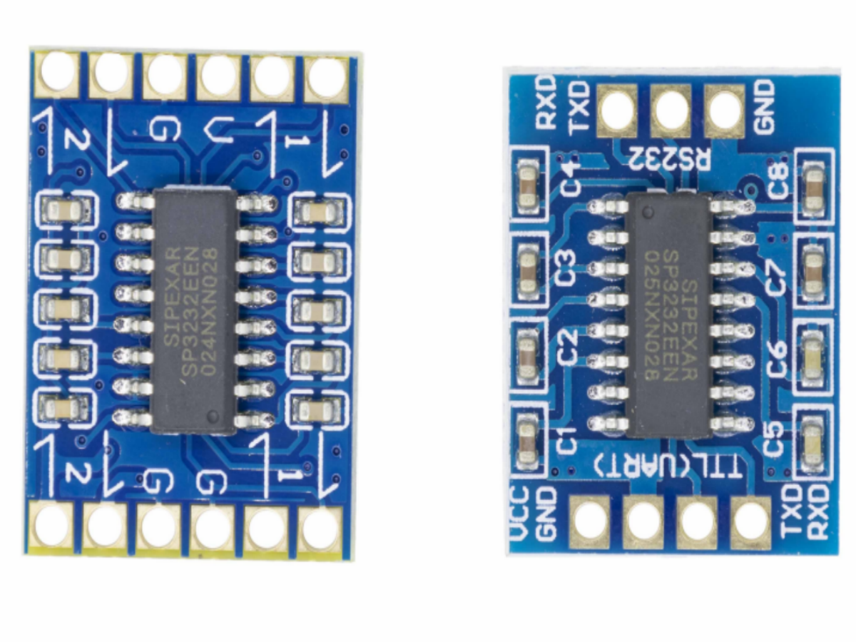
At its core, the SP3232 module is a tiny circuit built around the Exar SP3232 chip—hence the name. Its only job? Convert TTL signals to RS232 levels and back. Why does that matter? Most microcontrollers (MCUs) like Arduino or ESP32 use TTL for serial communication, but a lot of older or industrial devices still rely on RS232. Plugging TTL directly into RS232? You’ll fry your MCU faster than you can say “baud rate.”
The SP3232’s big selling point? It’s dual-channel. That means you can run two separate serial connections at once—say, one from your Arduino to a PC and another to a temperature sensor—without needing two separate modules. It also skips the bulky inductors other RS232 chips need, using tiny charge pumps to generate RS232 voltages from a single 3.3V or 5V supply. Perfect for tight project enclosures.
What is the SP3232E TTL-to-RS232 Module?


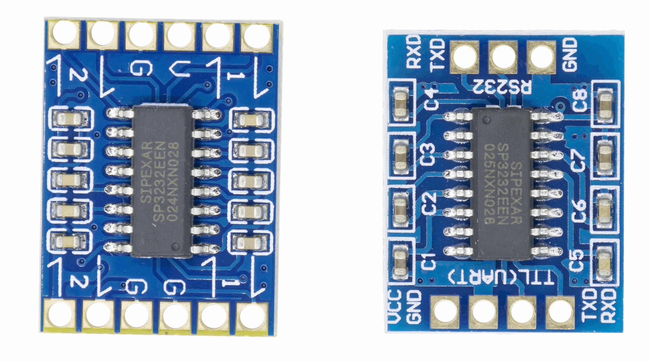
The SP3232E module is a compact, single-supply solution built around the SP3232E dual-channel RS232 transceiver. Its primary function is converting TTL/CMOS levels (3.0V–5.5V) to RS232-compliant ±5.5V levels and vice versa—a critical translation, as direct connection between TTL and RS232 devices risks permanent damage due to incompatible voltage ranges. A key distinction of the SP3232E (per datasheet) is its integrated charge pump that eliminates external inductors, generating RS232 voltages from a single 3.0V–5.5V supply.It supports two full-duplex UART channels, enabling simultaneous communication between a microcontroller and two RS232 devices (e.g., a PC and an industrial sensor). The module also features TTL tri-state outputs, which prevent bus contention when multiple devices share the same communication line—a detail often overlooked in generic guides but critical for system stability.
What inside the module?
| Component | Datasheet-Specified Details |
| SP3232E Transceiver Chip | 2 drivers, 2 receivers; TSSOP-16/SSOP-16 package |
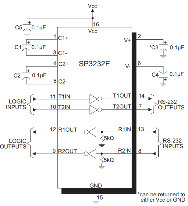
| Charge Pump Capacitors | 4 * 0.1µF external capacitors (C1+, C1–, C2+, C2–) |
| Voltage Regulator | 3.0V – 5.5V input, ripple rejection >40dB |
| Pull-Up/Pull-Down Resistors | 10kΩ typical; connected to TTL input pins |
| ESD Protection Diodes | ±15kV HBM, ±8kV IEC 61000-4-2 contact discharge |
| LED Indicators | Power (VCC) and Tx/Rx activity LEDs |
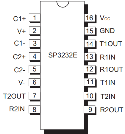
Pinout & Definition:How to wire it?
| Pin No. | Pin Label | Description |
| 1 | C1+ | Positive terminal of the voltage doubler charge-pump capacitor |
| 2 | V+ | 5.5V output generated by the charge pump |
| 3 | C1- | Negative terminal of the voltage doubler charge-pump capacitor |
| 4 | C2+ | Positive terminal of the inverting charge-pump capacitor |
| 5 | C2- | Negative terminal of the inverting charge-pump capacitor |
| 6 | V- | -5.5V output generated by the charge pump |
| 14 | T1OUT | RS-232 driver output |
| 7 | T2OUT | RS-232 driver output |
| 13 | R1IN | RS-232 receiver input |
| 8 | R2IN | RS-232 receiver input |
| 12 | R1OUT | TTL/CMOS receiver output |
| 9 | R2OUT | TTL/CMOS receiver output |
| 11 | T1IN | TTL/CMOS driver input |
| 10 | T2IN | TTL/CMOS driver input |
| 15 | GND | Ground |
| 16 | Vcc | 3.0V to 5.5V supply voltage |
Pro Tip: If you’re connecting to a PC (which rarely has RS232 ports anymore), use an RS232 to USB converter (I prefer FTDI-based ones—they’re driver-friendly). The converter’s DB9 port plugs into your SP3232’s RS232 pins, and the USB side goes to your PC.
Key Specification
| Spec | Details |
| Supply Voltage | 3.0V-5.5V (works with both 3.3V and 5V MCUs—no voltage dividers needed). |
| RS232 Output Voltage | ±5.5V (meets RS232 standards—works with all RS232 devices). |
| Data Rate | Up to 1Mbps (handles all common RS232 baud rates: 9600, 19200, 115200bps). |
| Operating Temperature | -40°C to +85°C (industrial grade—works in garages or freezers). |
| ESD Protection | ±15kV (Human Body Model)—safe to handle without anti-static gear (but still be careful). |
| Power Use | 5mA active, 1µA shutdown (won’t drain batteries in portable projects). |
Step-by-Step Usage Guide
Follow these steps to ensure compliance with the SP3232E’s operating requirements and avoid damage:
Step 1: Gather Components
- SP3232E module (with pre-soldered 0.1μF capacitors)
- Microcontroller (likeArduino Uno, ESP32)
- RS232 to USB converter (FTDI-based recommended)
- DB9 RS232 cable (straight-through)
- Jumper wires (24AWG or similar)
- 3.3V/5V power supply (matching MCU voltage)
Step 2: Wiring (Single-Channel Example)
| SP3232E Pin | Arduino Uno Pin | RS232 to USB Converter (DB9) |
| VCC | 5V | N/A |
| GND | GND | Pin 5 (GND) |
| TTL_TX1 (T1IN) | D0 (Rx) | N/A |
| TTL_RX1 (R1OUT) | D1 (Tx) | N/A |
| RS232_TX1 (T1OUT) | N/A | Pin 2 (Rx) |
| RS232_RX1 (R1IN) | N/A | Pin 3 (Tx) |
For 3.3V MCUs (like ESP32), connect VCC to 3.3V instead of 5V. Never mix voltage levels—this violates the datasheet’s absolute maximum ratings and will damage the chip.
Step 3: Driver Installation
The SP3232E module requires no dedicated drivers. For RS232 to USB converters: FTDI-based converters: Install FTDI VCP drivers (available at ftdichip.com).Prolific-based converters: Use Prolific PL2303 drivers. Windows 10/11 often auto-installs these, but verify via Device Manager.
Step 4: Test Communication
1.Upload this UART sketch to the Arduino (matches datasheet-recommended baud rates):
					void setup() {
  Serial.begin(9600); // Match this baud rate in your PC software
}

void loop() {
  Serial.println("Hello from SP3232!");
  if (Serial.available() > 0) {
    String msg = Serial.readString();
    Serial.print("You sent: ");
    Serial.println(msg);
  }
  delay(1000);
}
2.Open TeraTerm or Arduino IDE Serial Monitor: Select the RS232 port (from USB converter).
3.Set parameters: 9600bps, 8 data bits, 1 stop bit, no parity (8N1—datasheet default).
4.Verify communication: The PC should receive “SP3232E Test…” every second. Sending a message from the PC will trigger an echo from the Arduino.
SP3232E vs SP3232 vs MAX232
| Feature | SP3232E | SP3232 (Legacy) | MAX232 |
| Supply Voltage | 3.0V – 5.5V | 4.5V – 5.5V | 4.5V – 5.5V |
| Data Rate | 1000kbps | 200kbps | 120kbps |
| External Caps | 4 x 0.1 µF | 4 x 1 µF | 5 x 1 µF |
| ESD Protection | ±15kV HBM | ±10kV HBM | ±15kV HBM (varies by variant) |
| Shutdown Current | ≤1 µA | ≤5 µA | No shutdown |
The SP3232E outperforms both in speed, voltage flexibility, and power efficiency—making it the clear choice for modern projects.
Application Cases
The SP3232E’s specifications make it suitable for these industrial and hobbyist use cases:
1: Industrial Sensor Data Logging
Connect two RS232 pressure sensors to an ESP32 via the SP3232E’s dual channels. The module’s -40°C to +85°C operating range ensures reliability in factory environments, while 1Mbps data rate captures high-frequency sensor readings. The ESP32 transmits logged data to the cloud via Wi-Fi.
2: Retro CNC Machine Control
Link a vintage CNC mill (RS232 port) to a Raspberry Pi (3.3V TTL) using the SP3232E. The module’s ±15kV ESD protection safeguards against static in workshops, and TTL tri-state outputs prevent signal conflicts when sending G-code from the Pi to the mill.
3: Medical Device Communication
In low-power medical monitors, the SP3232E’s 1μA shutdown current extends battery life. Its compliance with EIA/TIA-232-F ensures accurate data transmission between the monitor (TTL) and a central RS232 database.
FAQS
Can I use 1μF capacitors instead of 0.1μF?
No. The datasheet specifies 0.1μF for charge pump stability. Larger capacitors will increase voltage ripple and may damage the chip.
Why is my RS232 output voltage only ±3V?
Check the charge pump capacitors—missing or incorrect values cause insufficient voltage generation. Verify all four 0.1μF caps are soldered correctly.
Can the SP3232E communicate with 2.7V TTL devices?
Yes. It can compatibility with 2.7V RS232 devices, as its receiver threshold is ≤0.8V (low) and ≥2.0V (high).
What’s the maximum cable length at 115200bps?
~50 feet (15 meters), per datasheet’s cable capacitance limit of 2500pF.


