
From the precise movement of smart cars and the smooth rotation of drone gimbals to the stepless dimming of LED lights, PWM speed control modules are ubiquitous. By adjusting the duty cycle of a square wave signal, they achieve fine control over output power, with core advantages of high control accuracy and low energy consumption.
In contrast, traditional series resistance speed control operates on a simple and crude principle: it divides the voltage by dissipating excess electrical energy through a resistor. This method not only squanders precious energy by converting it directly into waste heat, leading to significant overheating and energy loss, but its control process is also extremely coarse, making it impossible to achieve linear, smooth, and precise control.
The "switching" control of PWM, however, has completely changed this landscape. By switching on and off at extremely high frequencies, it generates minimal excess heat while precisely controlling the average voltage, thus driving the load with high efficiency. This combination of efficiency and precision has made it an indispensable core tool in modern electronic control.
PWM (Pulse Width Modulation) or modulation with the width of an impulse, is a widespread term in the world of electrical engineering. It generates a square wave signal via digital control, which switches between on and off states. By changing the ratio of the time the signal is "on" to the time it is "off," this on-off pattern can simulate a voltage between the board's full voltage (e.g., 5V on a UNO board, 3.3V on a MKR board) and off (0 volts). The time the signal is in the "on" state is called the pulse width. To obtain different analog values, you need to change or modulate this pulse width. For example, if you repeat this on-off pattern at a fast enough rate to control an LED, the effect is as if the signal is providing a stable voltage between 0 and Vcc, thereby controlling the LED's brightness.
 2")
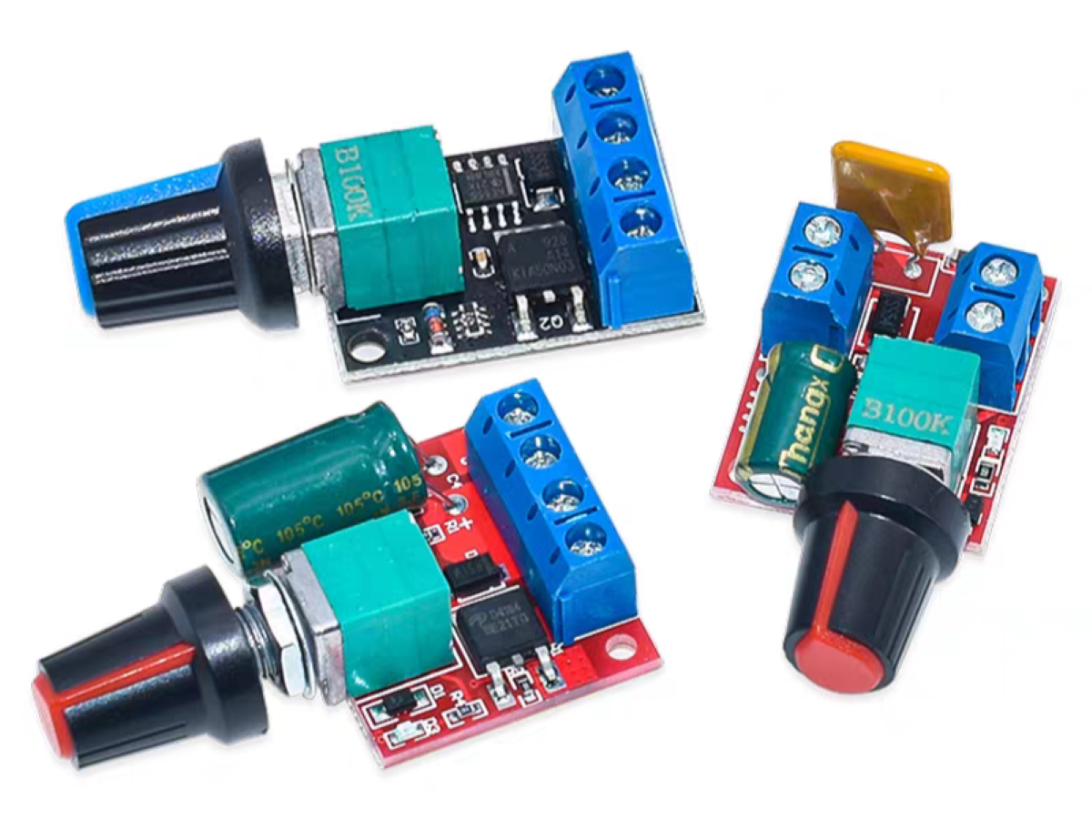
When choosing a PWM speed control module, match it to your specific requirements, paying close attention to its maximum input voltage and current range. We recommend modules with a self-resetting fuse. This fuse trips during an overcurrent situation and automatically resets after cooling, which effectively prevents the module from being burned out.
The PWM speed control module has four ports: two for power and two for output.
 3")
The power port has positive (+) and negative (-) terminals and must not be connected in reverse. When the load is a DC motor, reversing the polarity of the output terminals will not damage the load; it will only change the motor's direction of rotation. However, if the load is an LED, you must pay close attention to the output polarity, as an incorrect connection could burn out the load.
Now, let's look at an example: using a PWM speed control module to control the speed of a single motor.
You might be asking, "If one PWM speed controller can only run one motor, wouldn't I need four modules to control four motors? That's so inconvenient. Is there an easier way?"
Yes, there is! And the solution is simple: all you need is a breadboard.
Take a look at the diagram below.
 4")
By using the features of a breadboard, we can connect all the positive terminals of the four motors together, and do the same for all the negative terminals. This setup allows a single speed control module to control four motors. Now, let's see a demonstration of the result.
Finally, I used a PWM speed control module to build a simple speed-controlled car. Let's check it out together!
If you're interested in this module, you can click the blue text to go to our store and make a purchase. Trust me, you'll love it.
No account yet?
Create an Account