- Development Boards
- DC
- Sensors
- Hall Effect Sensor
- touch switch
- Vibration Sensor
- Temperature sensor
- Photoresistor
- MQ Sensor Series
- Color sensor
- water level sensor
- stepper motor
- Buzzer
- Inclinometer
- Accelerometer
- Current & Voltage
- Infrared
- Flame
- Ultrasonic
- Pressure & Altitude
- Temperature & Humidity
- Color,Light,lmage
- Shake,Force,Bend
- Identity
- GPS & Location
- Biometric
- IMU,AHRS
- Contact
- Pulse Oximeter and Heart Rate Sensor
- Motion
- Touch
- Pressure and Temperature
- Gas Sensor
- Modules
- Displays
- Wireless & loT
- Power & Batteries
- Robotics
- Tools & Equipments
- Components
Table of Contents
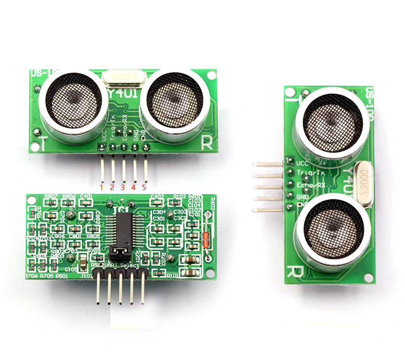
Introduction to the US-100 Ultrasonic Ranging Module
The US-100 Ultrasonic Ranging Module enables non-contact distance measurement with a range of 2cm to 4.5m. It features a wide voltage input range of 2.4V to 5.5V and a static power consumption of less than 2mA. Equipped with a built-in temperature sensor, it corrects distance measurement results. Additionally, it supports multiple communication methods such as GPIO and UART, and includes a watchdog timer for stable and reliable operation.
Main Technical Parameters
| Electrical Parameters | US-100 Ultrasonic Ranging Module |
|---|---|
| Operating Voltage | DC 2.4V~5.5V |
| Quiescent Current | 2mA |
| Operating Temperature | -20~+70 °C |
| Output Mode | Level or UART (selected by jumper cap) |
| Induction Angle | Less than 15 degrees |
| Detection Distance | 2cm-450cm |
| Detection Accuracy | 0.3cm+1% |
| Serial Port Configuration in UART Mode | Baud rate 9600, 1 start bit, 1 stop bit, 8 data bits, no parity, no flow control. |
Interface Description
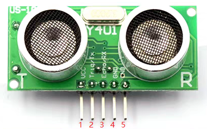
| PIN NUMBER | FUNCTION DESCRIPTION |
|---|---|
| Pin 1 | Connect to VCC power supply (power supply range: 2.4V - 5.5V) |
| Pin 2 | When in UART mode, connect to the TX terminal of the external circuit's UART; when in level-triggered mode, connect to the Trig terminal of the external circuit |
| Pin 3 | When in UART mode, connect to the RX terminal of the external circuit's UART; when in level-triggered mode, connect to the Echo terminal of the external circuit |
| Pin 4 | Connect to the ground of the external circuit |
| Pin 5 | Connect to the ground of the external circuit |
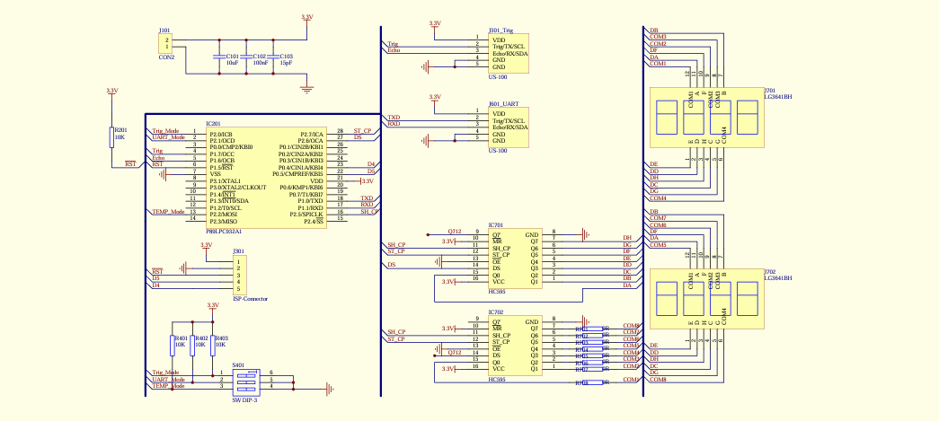
US-100 Schematic Diagram
Working Principle of Level-Triggered Ranging
Before powering on the module, first remove the jumper cap from the mode selection jumper to set the module to the level-triggered mode.
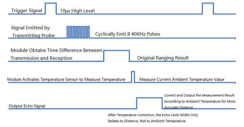
Just input a high level of more than 10 microseconds (μs) into the Trig/TX pin, and the system will emit 8 ultrasonic pulses of 40 kilohertz (KHZ). Then, it will detect the echo signal. After detecting the echo signal, the module will also measure the temperature value, correct the distance measurement result based on the current temperature, and output the corrected result through the Echo/RX pin.
In this mode, the module converts the distance value into twice the time value corresponding to a sound speed of 340 meters per second (m/s), and outputs a high level through the Echo pin. The distance value can be calculated based on the duration of this high level. That is, the distance value is: (Duration of high level × 340 m/s) / 2.
Note: Since the distance value has been corrected by temperature, there is no need to correct the ultrasonic sound speed according to the ambient temperature at this time. In other words, regardless of the temperature, the sound speed can be set to 340 m/s.
Working Principle of UART-Triggered Ranging
Before powering on the module, first plug the jumper cap onto the mode selection jumper to set the module to UART-triggered mode.
In this mode, you only need to input 0X55 (with a baud rate of 9600) into the Trig/TX pin, and the system will emit 8 ultrasonic pulses of 40 KHZ, then detect the echo signal. After detecting the echo signal, the module will also measure the temperature value, correct the distance measurement result based on the current temperature, and output the corrected result through the Echo/RX pin.
The output distance value consists of two bytes in total: the first byte is the high 8 bits of the distance (HData), and the second byte is the low 8 bits of the distance (LData), with the unit being millimeters (mm). That is, the distance value is (HData * 256 + LData) mm.
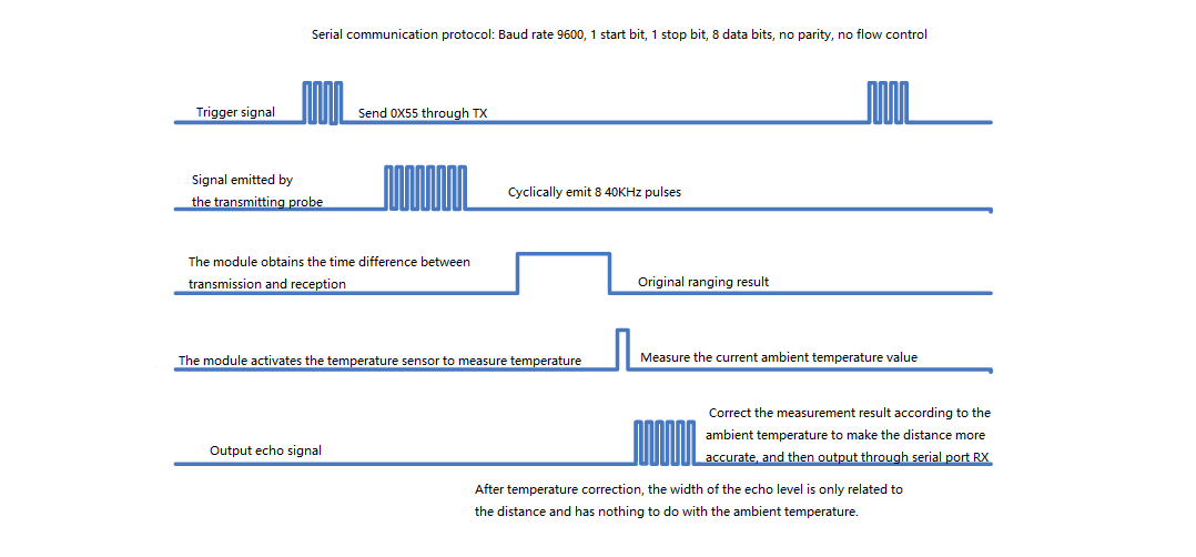
Working Principle of UART-Triggered Temperature Measurement
Before powering on the module, first plug the jumper cap onto the mode selection jumper to set the module to UART-triggered mode.
In this mode, you only need to input 0X50 (with a baud rate of 9600) into the Trig/TX pin, and the system will activate the temperature sensor to measure the current temperature, then output the temperature value through the Echo/RX pin.
After the temperature measurement is completed, the module will return a 1-byte temperature value (TData). The actual temperature value is calculated as TData - 45. For example, after sending 0X50 via TX, if 0X45 is received at the RX terminal, the temperature at this time is [69 (the decimal value of 0X45) - 45] = 24 degrees Celsius.

US100_GPIO_Arduino
					unsigned int EchoPin = 2;           // connect Pin 2(Arduino digital io) to Echo/RX at US-100
unsigned int TrigPin = 3;           // connect Pin 3(Arduino digital io) to Trig/TX at US-100
unsigned long Time_Echo_us = 0;
unsigned long Len_mm  = 0;
void setup()
{  //Initialize
    Serial.begin(9600);                        //Serial: output result to Serial monitor
    pinMode(EchoPin, INPUT);                    //Set EchoPin as input, to receive measure result from US-100
    pinMode(TrigPin, OUTPUT);                   //Set TrigPin as output, used to send high pusle to trig measurement (>10us)
}

void loop()
{
    digitalWrite(TrigPin, HIGH);              //begin to send a high pulse, then US-100 begin to measure the distance
    delayMicroseconds(50);                    //set this high pulse width as 50us (>10us)
    digitalWrite(TrigPin, LOW);               //end this high pulse

    Time_Echo_us = pulseIn(EchoPin, HIGH);               //calculate the pulse width at EchoPin,
    if((Time_Echo_us < 60000) && (Time_Echo_us > 1))     //a valid pulse width should be between (1, 60000).
    {
      Len_mm = (Time_Echo_us*34/100)/2;      //calculate the distance by pulse width, Len_mm = (Time_Echo_us * 0.34mm/us) / 2 (mm)
      Serial.print("Present Distance is: ");  //output result to Serial monitor
      Serial.print(Len_mm, DEC);            //output result to Serial monitor
      Serial.println("mm");                 //output result to Serial monitor
    }
    delay(1000);                            //take a measurement every second (1000ms)
}


