Back to products
Line-Tracking Module
Line-Tracking Module Price range: $0.89 through $3.59

NE555 Pulse Generator, A Small Signal Generator Module

Price range: $0.99 through $2.491 pcs

Dimensions N/A
Brand

easyelecmodule

SKU: N/A Category: Tag:
DESCRIPTION AND FEATURES

Product Introduction

This NE555 pulse generator module is a signal generator that generates square wave signals for experimental development. The generated pulses are adjustable and can be used to generate square wave signals to drive stepper motor drivers.

NE555 Pulse Generator Module

NE555 frequency – adjustable pulse generator module. The default shipping frequency range is adjustable from 2K to 25KHz. The frequency range is determined by capacitor C1. You can replace capacitor C1 by yourself to change the adjustable range. When the capacitance increases, the frequency decreases. Pay attention not to have overcurrent during signal output, otherwise the chip will be damaged. Add a current – limiting resistor to the output to prevent overload damage.

Product Parameters

  1. On – board NE555 chip;
  2. Single – channel signal output, and the output duty cycle is approximately a square wave of fifty percent;
  3. On – board adjustable resistor. Adjusting the resistance value can control the output frequency, and the default range is adjustable from 2K to 25KHz;
  4. Operating voltage: 5V – 12V;
  5. Board size: 29mm * 12mm;
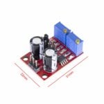
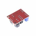
NE555 Pulse Duty Cycle Adjustable Generator

Product Features

  1. The output is equipped with an LED indicator, making the presence or absence of output straightforward (the LED is on at low level, off at high level, and flashes when the frequency is relatively low);
  2. Optional output frequency range gears make the output frequency more continuously adjustable;
     

    Low – frequency gear: 1Hz – 50Hz


    Medium – frequency gear: 50Hz – 1kHz


    Medium – high – frequency gear: 1kHz – 10kHz


    High – frequency gear: 10kHz – 200kHz

  3. The output duty cycle can be fine – tuned. The duty cycle and frequency are not adjustable separately, and adjusting the duty cycle will change the frequency;
  4. The output frequency is adjustable: The period T = 0.7 (RA + 2RB) C. RA and RB are adjustable from 0 to 10K; C = 0.001UF in the low – frequency gear; C = 0.1UF in the medium – frequency gear; C = 1UF in the medium – high – frequency gear; C = 100UF in the high – frequency gear; When powered by 5V, the output current is about 15mA, and when powered by 12V, the output current is about 35mA. The power supply voltage range is 5V – 15VDC.

Product Parameters

PARAMETER DESCRIPTION
Size 31mm*22mm
Main Chip NE555
Input Voltage 5V – 15VDC. When powered by 5V, the output current can be around 15mA; when powered by 12V, the output current can be around 35mA.
Input Current ≥100mA
Output Amplitude 4.2V V-PP to 11.4V V-PP (The output amplitude varies according to the input voltage). Output current: ≥15mA (when powered by 5V and V-PP is greater than 50%); ≥35mA (when powered by 12V and V-PP is greater than 50%).

Product Parameters

  1. Size: 40mm * 20mm;
  2. Function: Generates square waves or rectangular waves of different frequencies;
  3. Power supply: Input voltage 5 – 12VDC. When powered by 5V, the output current can be around 10mA; when powered by 12V, the output current can be around 30mA;
  4. Frequency: 5 frequency segments (measured values)
     
    J1 gear: 0.6Hz – 25Hz
     
    J2 gear: 7Hz – 300Hz
     
    J3 gear: 50Hz – 2.5kHz
     
    J4 gear: 350Hz – 6.6kHz
     
    J5 gear: 6.7kHz – 180kHz
     
    Adjustable duty cycle range: 0.4 – 0.99
  5. LED output indication: The LED lights up at low level and goes out at high level. The speed of LED flashing indicates the change of frequency output. In addition to selecting different frequency segments with jumpers, RV1 adjustment can adjust the frequency. The flashing of the LED during adjustment can be regarded as the corresponding frequency change with the adjustment change;
  6. Input current: ≥100mA;
  7. Output voltage: 4.2V – 11.4V peak (varies with supply voltage);
  8. Output frequency calculation formula: Period T = 0.7 (Ra + 2Rb) C. Ra and Rb are adjustable from 0 to 10K;
  9. Input: VCC, GND. Output: VCC, OUT, GND. Here, the input voltage is consistent with the output, which is for the convenience of users and can be used for subsequent power supply. OUT is the output frequency signal.

Product Application Scope

  1. Used as a square wave signal generator to generate square wave signals for experimental development.
  2. Used to generate square wave signals to drive stepper motor drivers.
  3. Generate adjustable pulses for MCU use.
  4. Generate adjustable pulses to control related circuits.

Precautions:

When using jumper caps to change the frequency, please power off first, and then power on again after the jumper caps are connected.

If you want to learn more details,you can refer to this datasheet:https://easyelecmodule.com/wp-content/uploads/ne555-datasheet-1.pdf

Reviews (0)

Reviews

There are no reviews yet.

Be the first to review “NE555 Pulse Generator, A Small Signal Generator Module”

Your email address will not be published. Required fields are marked *

Shipping and Delivery

Shipping Cost

We only ship to the United States. Shipping costs are calculated based on the total order amount.

Shipping Method And Delivery Time

All orders will be processed and shipped within 72 hours of placing the order (excluding weekends and holidays). They will ship from Shenzhen, China, primarily via 4PX logistics. Depending on the destination and logistics conditions, other carriers such as DHL, FedEx, UPS, USPS, etc., may also handle the delivery. Estimated shipping time is 7-12 business days, with actual delivery occurring in 10-17 business days, depending on logistics conditions.

Payment:

We accept Visa, Master card, Maestro, American Express, JCB, Dinner's Club, Discover, Paypal, Apple Pay, Google Pay .