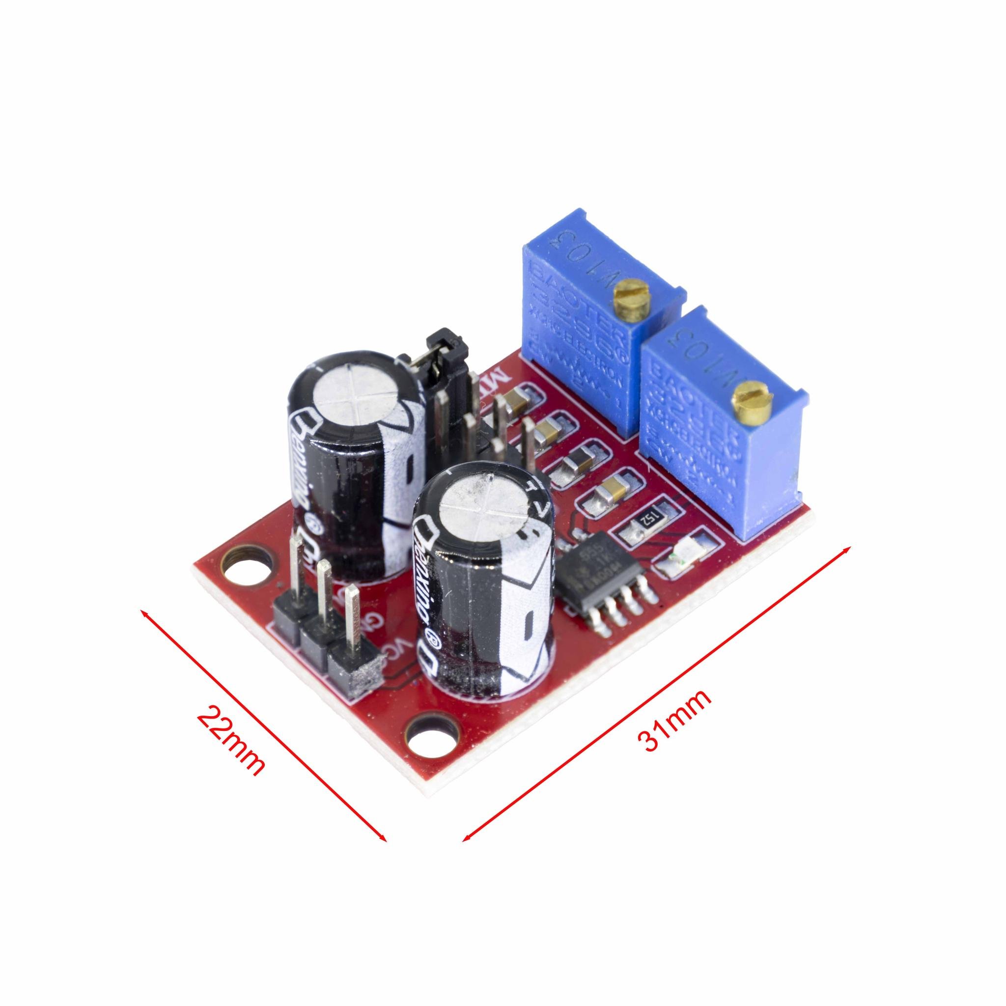
NE555 Pulse Duty Cycle Adjustable Generator
$1.451 pcs

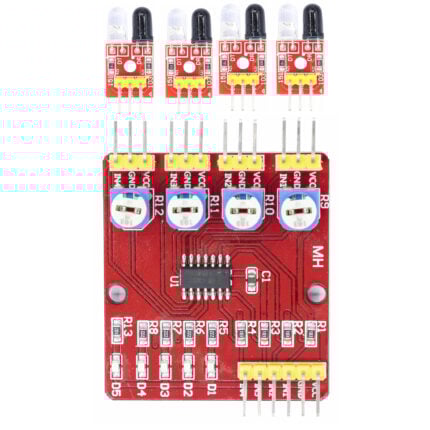
IR Infrared Module
$1.001 pcs
E18-D80NK Photoelectric Switches(Line Tracking)
$3.201pcs
The E18-D80NK photoelectric switch uses infrared sensing for non-contact object detection. It offers adjustable sensing distance and stable performance, making it suitable for automation control and obstacle detection applications.
| Dimensions | 50 × 18 mm |
|---|---|
| Brand |
easyelecmodule |
2631 in stock


Reviews
There are no reviews yet.