Table of Contents
With the development of energy industry, batteries have gradually become the core power source for electric vehicles (EVs), energy storage systems (ESSs), medical equipment, and consumer electronics in our lives. As the “manager” of batteries, the battery management system (BMS) plays a crucial role—its accurate selection directly determines the safety, service life, and energy utilization efficiency of batteries.
An undersized BMS will cause current limiting; a wrongly selected one may lead to overcharge and over-discharge risks; and an overpriced one will result in cost waste. Therefore, selecting a BMS is not a simple process of matching parameters, but a comprehensive decision-making process based on battery characteristics, system scale, and application scenarios. Now, let’s take a detailed look at how to select the most suitable BMS for you.
Battery Type Compatibility
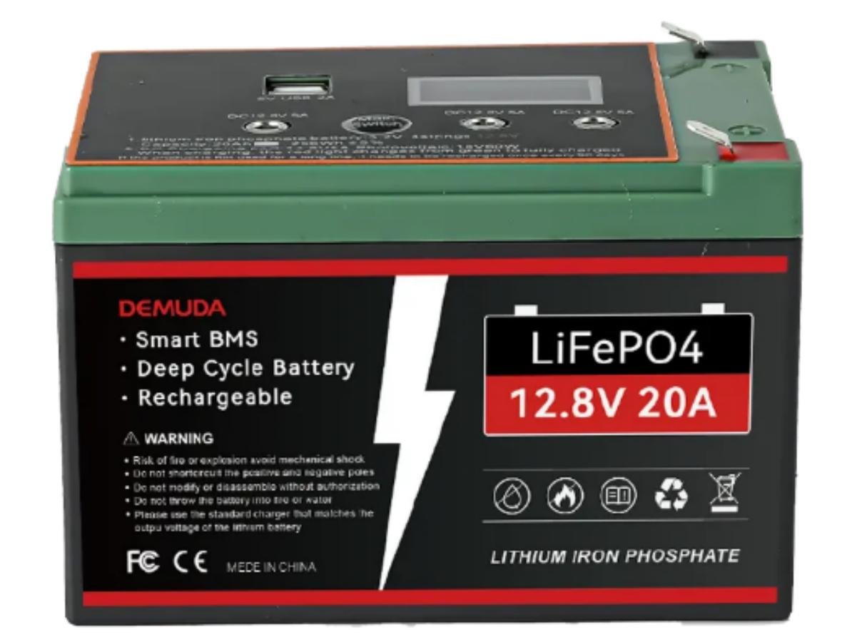
First, you must clarify the type of your battery. As the “manager” of the battery, the BMS needs to be compatible with the specific battery type—it will cause significant troubles if this factor is ignored. On the market, there are specialized products such as “Daly LiFePO4 BMS”, “18650 Li-ion BMS”, and “Lead-Acid BMS”—there is no “universal BMS”. Forced mixing of BMS and battery types will only lead to battery failure or safety accidents.
Reasons
- Nominal voltage per cell and cut-off voltages for charging/discharging vary completely among different batteries
Battery Type | Nominal Voltage per Cell | Charge Cut-off Voltage (per cell) | Discharge Cut-off Voltage (per cell) | Correspondence between Typical System Voltage and Number of Series Cells |
LiFePO4 (Lithium Iron Phosphate) | 3.2V | 3.65~3.7V | 2.5~2.8V | 12V = 4S (3.2V×4), 24V = 8S, 48V = 16S |
Li-ion (Ternary Lithium, etc.) | 3.7V | 4.2~4.35V | 2.75~3.0V | 12V = 3S (3.7V×3), 24V = 6S, 48V = 13S |
LTO (Lithium Titanate Oxide) | 1.5V | 2.0~2.3V | 1.0~1.2V | 12V = 8S (1.5V×8), 24V = 16S, 48V = 24S |
Lead-Acid Battery | 2.0V | 2.3~2.4V | 1.75~1.8V | 12V = 6S (2.0V×6), 24V = 12S, 48V = 24S |
Note: The nominal voltage per cell is an approximate voltage value when the battery operates under specified standard conditions. Determined by the battery’s electrochemical system, it is used to indicate the appropriate voltage for the battery.
Key Impact:
If you use a 4S BMS for LiFePO4 (suitable for 12V systems) on a 12V Li-ion (ternary lithium) system, the BMS will falsely detect “4-series voltage”. In reality, a 12V Li-ion system only has 3 series cells, leading to deviations in total voltage judgment and failure of overvoltage/undervoltage protection. For example, Li-ion batteries need to be charged to 4.2V per cell (total 12.6V), but the LiFePO4 BMS may only trigger protection when reaching 3.65V per cell (total 14.6V)—this far exceeds the tolerance limit of Li-ion batteries, directly causing overcharge-induced bulging and safety accidents. If you use a 12V lead-acid BMS (6S) on a 12V LiFePO4 system (4S), the BMS will report an error due to “detecting 2 missing series cells” or misjudge it as a battery fault, resulting in failure to work normally.
- Thermal stability, overcharge/over-discharge tolerance, and chemical reaction risks vary completely among different batteries
Battery Type | Core Risk of Chemical Properties | Safety Design Required for BMS Matching |
LiFePO4 | Good thermal stability (decomposition temperature > 200℃), but overcharging will damage the positive electrode structure | Overcurrent protection can be moderately relaxed; temperature protection threshold is relatively high (usually 60~70℃) |
Li-ion (Ternary Lithium) | Poor thermal stability (decomposition temperature 120~180℃); overcharging/overcurrent easily causes fire and explosion | More sensitive overcurrent protection; strict temperature protection (usually 50~60℃); faster circuit cutoff required |
LTO (Lithium Titanate Oxide) | Extremely high thermal stability (decomposition temperature > 300℃), but sensitive to low-temperature performance | Overcurrent protection can be more relaxed, but “low-temperature discharge current limitation” must be added (to prevent sudden capacity drop caused by high current at low temperatures) |
Lead-Acid Battery | Overcharging easily causes water loss and sulfation; over-discharging easily leads to plate softening | “Overcharge time protection” must be added (to prevent water loss due to long-term float charging); strict discharge cut-off voltage (to avoid sulfation caused by voltage < 1.75V per cell) |
Example:
If a Li-ion (ternary lithium) BMS is used for LiFePO4, it will frequently cut off power supply due to “excessively low temperature protection threshold (50℃)”, making LiFePO4 unable to work in normal high-temperature environments (such as outdoor areas in summer). Conversely, if a LiFePO4 BMS is used for Li-ion (ternary lithium), it will miss the fire warning opportunity due to “delayed temperature protection (70℃)”.

- Charging curves, discharge characteristics, and capacity attenuation laws vary among different batteries
Differences in Charging Algorithms
- LiFePO4: Charging requires going through the process of “high-current constant current (CC) → constant voltage (CV) after reaching 3.65V → cut-off when current drops to 0.05C”. Using the lead-acid “constant voltage float charging” algorithm will cause overcharging of LiFePO4.
- Lead-Acid Battery: Charging requires “stage constant current → constant voltage float charging (to compensate for water loss)”. Using the LiFePO4 “CV cut-off” algorithm will result in insufficient charging of the lead-acid battery and long-term sulfation.
- LTO: It has extremely strong charging acceptance (supports high-current fast charging), so the BMS must support “fast charging control above 10C”. However, the “low-current fast charging limitation” of ordinary Li-ion BMS will waste the fast-charging advantage of LTO.
Differences in SOC Calculation Models
- LiFePO4: It has good linearity between State of Charge (SOC) and voltage (2.5~3.65V corresponds to 0~100% SOC), so the BMS can estimate SOC through voltage.
- Li-ion (Ternary Lithium): The relationship between SOC and voltage is non-linear (3.7V may correspond to 50% or 70% SOC, depending on the number of cycles). The BMS must use “coulomb counter (current integration) + voltage compensation” for correction.
- If the SOC model of LiFePO4 is used to calculate the SOC of Li-ion (ternary lithium), it will lead to misjudgment such as “displaying 50% remaining power but actually being exhausted”.
Differences in Balancing Strategies
- High-series LiFePO4/Li-ion (e.g., 16S 48V): Inter-cell voltage differences will accelerate capacity attenuation, so the BMS must support “active balancing” (transferring power between cells through a chip).
- Lead-Acid Batteries/Low-series LTO: Inter-cell differences are small, so the BMS only needs “passive balancing” (discharging high-voltage cells through resistors) and does not require complex active balancing circuits.
- If a lead-acid “passive balancing BMS” is used for 16S LiFePO4, insufficient balancing capability will expand inter-cell differences, and the battery pack may fail within one year.
- Rated discharge current, maximum instantaneous current, and power density vary among different batteries
The “current sampling accuracy”, “power tube (MOS tube) selection”, and “overcurrent protection threshold” of the BMS must match the battery parameters—otherwise, it will cause BMS burnout or battery damage due to overcurrent.
Example: “LiFePO4 BMS 200A” is suitable for high-power LiFePO4 (e.g., RVs, energy storage), and its power tube must withstand a continuous current of 200A. “18650 Li-ion BMS 10S 40A” is suitable for low-power 18650 battery packs (e.g., laptops, small energy storage), and its power tube only needs to withstand 40A. If a 40A 18650 BMS is used in a 200A LiFePO4 system, the power tube will burn out due to overload, triggering a short-circuit risk.
Reference for BMS Matching with Batteries
- Specialized for LiFePO4 Batteries: BMS LiFePO4, LiFePO4 Battery Management System, Daly BMS LiFePO4, Victron LiFePO4 BMS, Pylontech LiFePO4 BMS, Volt Polska LiFePO4 BMS, Power Queen 12V 100Ah LiFePO4 BMS, Kepworth 12V 100Ah LiFePO4 BMS, Akumulator LiFePO4 12V 150Ah 150A BMS, Gtk LiFePO4 BMS, Mjbsan LiFePO4 BMS, Baterie Ultimatron LiFePO4 BMS.
- Specialized for Li-ion Batteries: BMS for Lithium Ion Battery, Lithium Ion Battery Management System, Li-ion BMS, 18650 Li-ion BMS, 21700 Li-ion BMS, Lithium Polymer (LiPo) BMS, BMS LiPo Battery.
- Specialized for LTO Batteries: BMS LTO Battery, LTO Battery Management System.
- Specialized for Lead-Acid Batteries: Lead Acid Battery BMS.

Voltage, Current, and Number of Series Cells
- Number of Battery Series Cells: Determines whether the BMS can accurately monitor each cell (core of safety)
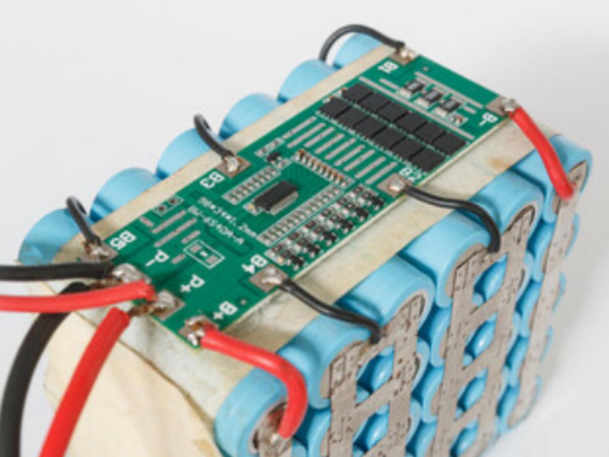
One of the core functions of the BMS is to monitor the voltage of individual cells and perform balancing. When cells are connected in series, the voltage of each cell will gradually become inconsistent due to differences in capacity and internal resistance (i.e., “cell imbalance”). If a cell is overcharged (e.g., a ternary lithium cell exceeds 4.2V) or over-discharged (e.g., a LiFePO4 cell drops below 2.5V), it will directly cause bulging, leakage, or even explosion.
- If the number of series cells supported by the BMS < the number of series cells in the battery pack: The BMS cannot monitor the uncovered cells. These cells may be damaged due to overcharging/over-discharging, further triggering safety accidents of the entire battery pack.
- If the number of series cells supported by the BMS > the number of series cells in the battery pack: The extra sampling channels will be idle, which not only increases costs but also may cause the BMS to falsely report faults due to “idle sampling channels”, resulting in failure to work normally.
Conclusion: The number of sampling channels of the BMS must completely match the number of series cells in the battery pack.
- Operating Voltage: Determines whether the BMS can work stably without damage (core of reliability)
The BMS itself needs to be powered within the voltage range of the battery pack to operate, and at the same time, it must withstand the maximum voltage of the battery pack without being broken down.
- If the upper limit of the BMS operating voltage < the maximum voltage of the battery pack: High-voltage components of the BMS (such as sampling chips and relays) will be broken down, leading to BMS burnout and even battery short circuits.
- If the lower limit of the BMS operating voltage > the minimum voltage of the battery pack: When the battery pack is discharged to the minimum operating voltage, the BMS will stop working due to insufficient power supply and cannot continue to protect the battery (e.g., failing to trigger over-discharge protection), resulting in battery damage due to over-discharging.
Conclusion: The operating voltage range of the BMS must completely cover the “minimum operating voltage ~ maximum operating voltage” of the battery pack.
- Operating Current: Determines whether the BMS can meet load requirements without overheating or overload (core of performance)
The BMS needs to control the charge-discharge current of the battery pack in real time. Mismatched current capability will lead to insufficient performance or safety risks.
- If the continuous current of the BMS < the required current of the load: The BMS will trigger overcurrent protection and force current limiting (e.g., an electric vehicle requires a peak current of 120A, but the BMS only supports 100A, making the vehicle unable to run at full power).
- If the continuous current of the BMS is much smaller than the peak current of the load: The current sampling resistor and MOS tube of the BMS will generate intense heat due to overload, which may burn out components and even cause fires.
Conclusion: The continuous charge-discharge current of the BMS must be ≥ the continuous required current of the load, and the peak current must be ≥ the instantaneous peak current of the load (it is recommended to keep a 1.2x margin to avoid instantaneous overload).
Category | Core Definition (BMS Side) | Relationship with Battery Pack |
Number of Battery Series Cells (Number of cells in series) | Number of cell sampling channels supported by the BMS (must completely match the number of cells in series in the battery pack) | Number of series cells in the battery pack = number of individual cells (e.g., a 16-series LiFePO4 battery pack = 16 3.2V LiFePO4 cells in series) |
Operating Voltage (System Voltage) | Voltage range in which the BMS can work stably (must cover the “minimum operating voltage ~ maximum operating voltage” of the battery pack) | System voltage of the battery pack = number of series cells × voltage per individual cell (e.g., 16-series LiFePO4: 16×3.2V = 51.2V nominal voltage, voltage range 48V~57.6V) |
Operating Current (Charge-Discharge Current) | The charge-discharge current value that the BMS can continuously withstand/control (including continuous current and peak current, which must match load requirements) | The charge-discharge current of the battery pack is determined by the load |

Common Parameter Models
Number of Battery Series Cells
- 1S-4S Low-Series BMS: Used for consumer electronics (e.g., mobile phones, power banks), small power tools (e.g., electric drills), and smart home devices.
Common models:
1S: BMS 1S 3.2V (LiFePO4), BMS 1S 3.7V (Li-ion) (suitable for single cells, commonly used in wearable devices);
3S-4S: BMS 3S 12V, BMS 4S 12V/14.4V (e.g., the CBM8580 chip from Sinhmicro supports 2-4 series, used in laptops and robot vacuums).
- 12S-16S Medium-High Series BMS: Used for energy storage systems (e.g., home energy storage), electric bicycles, and low-speed electric vehicles.
Common models:
12S 48V (suitable for 12-series LiFePO4 batteries (3.2V×12=38.4V), used in energy storage and electric tricycles);
13S 48V (suitable for 13-series Li-ion (ternary lithium) batteries (3.7V×13=48.1V), commonly used in low-voltage auxiliary batteries of electric vehicles);
16S 60V (suitable for 16-series LiFePO4 batteries (3.2V×16=51.2V), used in electric motorcycles and some energy storage systems).
- 20S and Above High-Series BMS: Used for high-voltage platforms of electric vehicles and large-scale energy storage power stations.
Common models:
20S 72V (suitable for 20-series Li-ion (ternary lithium) batteries (3.7V×20=74V), used in electric bicycles and light electric vehicles);
24S 72V (suitable for 24-series LiFePO4 batteries (3.2V×24=76.8V), used in energy storage systems and some commercial vehicles).
Operating Voltage
- 12V/24V Low-Voltage BMS: Used for automotive starter batteries, RV energy storage, and small off-grid systems.
Common models:
12V: BMS 12V 100A (compatible with lead-acid and lithium batteries, used in emergency automotive starting and home energy storage);
24V: BMS 24V 60A (suitable for 6-series LiFePO4 batteries (3.2V×6=19.2V), used in electric ships and industrial equipment).
- 48V Medium-Voltage BMS: Used for electric bicycles, energy storage systems, and backup power supplies for communication base stations.
Common models:
48V 100A (suitable for 13-series Li-ion (ternary lithium) batteries (3.7V×13=48.1V), supports fast charging and discharging, used in high-end electric bicycles);
48V 150A (suitable for 16-series LiFePO4 batteries (3.2V×16=51.2V), used in industrial and commercial energy storage systems).
- 72V and Above High-Voltage BMS: Used for electric vehicles, electric buses, and large-scale energy storage.
Common models:
72V 150A (suitable for 20-series Li-ion (ternary lithium) batteries (3.7V×20=74V), used in auxiliary batteries of electric vehicles);
60V 100A (suitable for 17-series Li-ion (ternary lithium) batteries (3.7V×17=62.9V), used in electric motorcycles and special vehicles).
Operating Current
- 10A-30A Small-Medium Current BMS: Used for consumer electronics, small power tools, and smart home devices.
Common models:
10A: BMS 1S 10A (used in mobile phone power banks and wireless earphones);
30A: BMS 4S 30A (suitable for 4-series lithium batteries (14.8V), used in electric screwdrivers and drones).
- 50A-100A Medium-High Current BMS: Used for electric bicycles, energy storage systems, and low-speed electric vehicles.
Common models:
50A: BMS 3S 50A (suitable for 3-series lithium batteries (11.1V), used in electric scooters);
100A: BMS 12S 100A (suitable for 12-series LiFePO4 batteries (38.4V), used in home energy storage and electric tricycles).
- 150A and Above High-Current BMS: Used for electric vehicles, electric buses, and large-scale energy storage.
Common models:
150A: BMS 20S 150A (suitable for 20-series lithium batteries (74V), used in high-voltage platforms of electric vehicles);
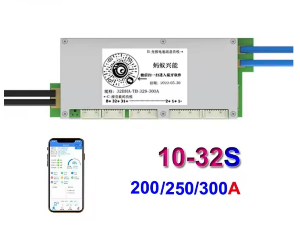
200A: BMS 8S 200A (suitable for 8-series lithium batteries (29.6V), used in electric forklifts and industrial equipment).
Product Purchase
https://easyelecmodule.com/product/battery-management-systems-bms-4s/
https://easyelecmodule.com/product/battery-management-systems-bms-16s/
https://easyelecmodule.com/product/battery-management-systems-bms-20s/
https://easyelecmodule.com/product/battery-management-systems-bms-relay-20s/
https://easyelecmodule.com/product/battery-management-systems-bms-22s/
For more models, please visit the official website
Pitfalls to Avoid in BMS Selection
- Only focusing on nominal voltage while ignoring voltage range: For example, using a BMS with a “50V nominal voltage” on a battery pack with a maximum voltage of 57.6V will cause the BMS to burn out due to overvoltage.
- Ignoring cell type: Using a ternary lithium BMS on a LiFePO4 battery pack will cause overcharging of LiFePO4 cells due to excessively high balancing thresholds.
- Matching current just to make do: Choosing a BMS with a current exactly equal to the load to save money will lead to severe heat generation of the BMS during long-term full-load operation and shorten its service life.
- Pursuing more functions is better: Selecting a BMS with CAN bus and active balancing for portable devices not only increases costs but also wastes resources.


