Introduction
If you’ve ever worked on projects involving microcontrollers like Arduino, ESP32, or ESP8266, you’ve likely needed a reliable way to bridge USB and UART communication. Enter the FT232RL—a flagship USB-to-UART IC from FTDI (Future Technology Devices International) that’s become a staple for hobbyists and professionals alike. In this blog, we’ll break down everything you need to know about the FT232RL: from its core features and hardware design to practical use cases, driver setup, and how it stacks up against alternatives like the CP2102. Let’s dive in!
What is the FT232RL?
At its core, the FT232RL is a single-chip USB-to-serial UART interface that simplifies adding USB connectivity to legacy serial devices or microcontroller projects. Unlike basic USB-to-TTL adapters, the FT232RL packs advanced features like built-in FIFO buffers, configurable I/O pins, and cross-platform driver support—all while minimizing external components (no need for an external crystal or USB termination resistors!).
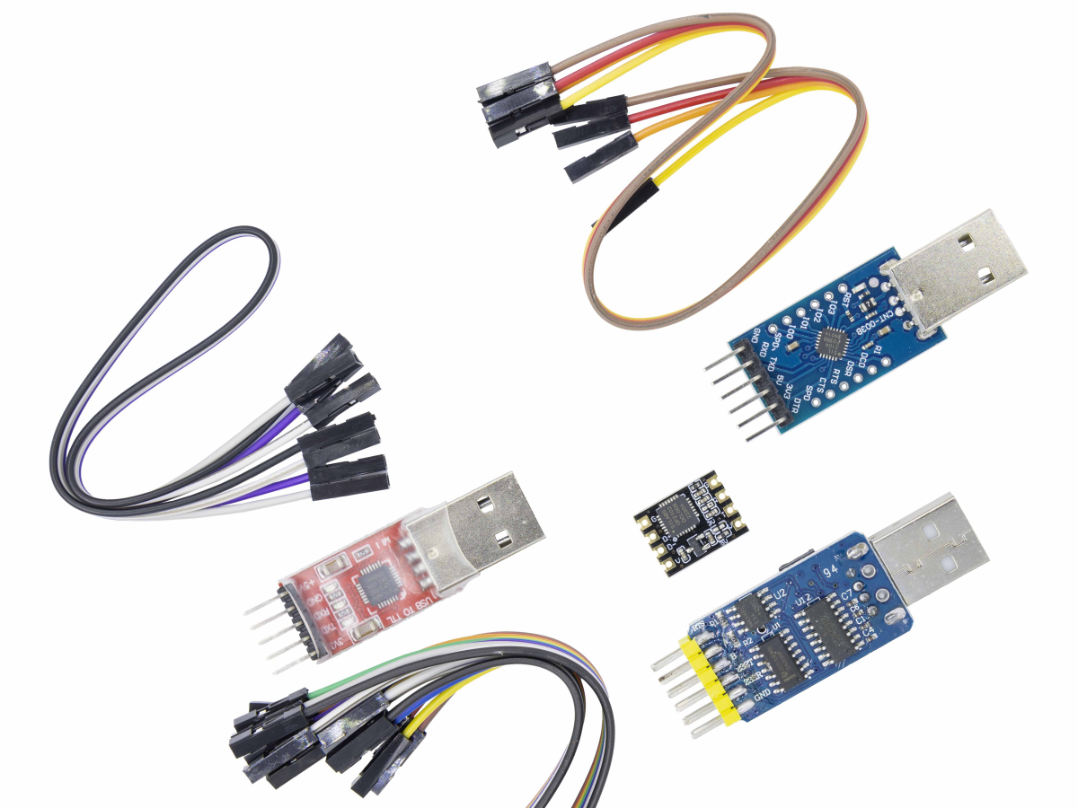
In addition, the common USB-to-serial port chips on the market mainly include four series: CP2102, CH340, FT232, and PL2303.
Main performance comparison:
| | CP2102/2103 | CH340 SERIES | FT232R | PL2303HXD |
|---|
| Manufacturer | Silicon | Nanjing Qinheng | FTDI | Prolific |
| Maximum Speed | 1M | 2M | 3M | 12M |
| Data Bits | 5, 6, 7, 8 | 5, 6, 7, 8 | 7, 8 | 5, 6, 7, 8 |
| Parity Bit | Even/Odd/None | Even/Odd/None | Even/Odd/None | Even/Odd/None |
| Stop Bits | 1, 1.5, 2 | 1, 2 | 1, 2 | 1, 1.5, 2 |
| Hardware Flow Control | Yes | Yes | Yes | Yes |
| Clock | Internal | Internal/External | Internal/External | Internal/External |
| Multi-port Support | Same series 2108 | Same series 342, 344 | Same series 2322, 4232 | |
| Stability | Good | Good | Best | Poor |
| Price | Medium | Low | High | Low |
- Handles the entire USB protocol on-chip (no USB firmware coding required).
- Supports baud rates from 300 baud to 3 Mbaud (ideal for high-speed serial communication).
- Integrates a 1024-bit EEPROM for storing device descriptors (e.g., USB VID/PID, serial number).
- Works with 1.8V–5V logic levels, making it compatible with most MCUs (Arduino, ESP32, ESP8266, etc.).
- Operates across Windows, Linux, macOS, and even Android (via J2xx drivers).
FT232RL Module Composition: What’s Inside?
While the FT232RL chip is the star, most users work with a FT232RL breakout board (or module) that simplifies wiring. A typical breakout board includes:
1、FT232RL IC: The main USB-to-UART controller (in a 28-pin SSOP package).
2、USB Port: A Type-B or micro-USB connector for PC/mobile connectivity.
3、Voltage Regulator: Converts USB 5V to 3.3V (some modules include a switch for 5V/3.3V output).
4、Indicator LEDs: TX (transmit) and RX (receive) LEDs to monitor data flow (powered by configurable CBUS pins).
5、Pin Headers: Exposed UART pins (TXD, RXD, RTS#, CTS#) and power pins (VCC, GND) for easy breadboarding.
6、EEPROM: Pre-programmed with FTDI’s default VID (0403h) and PID (6001h), plus a unique serial number.
FT232RL Pinout & Pin Definition
To use the FT232RL effectively, you need to understand its pinout. Below is the FT232RL pin diagram for the 28-pin SSOP package (common in breakouts), with critical pins explained:
| PIN NO. | PIN NAME | TYPE | DESCRIPTION |
|---|
| 1 | TXD | Output | UART transmit data (connect to MCU’s RXD pin, e.g., Arduino D0) |
| 5 | RXD | Input | UART receive data (connect to MCU’s TXD pin, e.g., Arduino D1) |
| 3 | RTS# | Output | Request to Send (hardware handshake; active low) |
| 11 | CTS# | Input | Clear to Send (hardware handshake; active low) |
| 15 | USBDP | I/O | USB data positive (includes internal 1.5kΩ pull-up resistor) |
| 16 | USBDM | I/O | USB data negative (includes internal series resistor) |
| 17 | 3V3OUT | Output | 3.3V regulator output (powers external logic; max 50mA) |
| 20 | VCC | Power | Core supply (4.0V-5.25V with internal oscillator; 3.3V with external crystal) |
| 4 | VCCIO | Power | UART/CBUS logic supply (1.8V-5.25V; match MCU’s logic level) |
| 7/18/21 | GND | Power | Ground (connect to MCU’s GND for common reference) |
| 19 | RESET# | Input | Active-low reset (leave unconnected or pull up to VCC if not used) |
| 22-23/12-14 | CBUS0-CBUS4 | I/O | Configurable pins (default: TXLED#, RXLED#, TXDEN, PWREN#, SLEEP#) |
FT232RL Schematic & Circuit Design
A basic FT232RL circuit for USB-to-UART communication is straightforward—here’s a simplified schematic (common in breakout boards):
1、USB Interface: USBDP/USBDM connect directly to the USB port (no external resistors needed, thanks to on-chip integration).
2、Power Supply: VCC (5V) from USB feeds the FT232RL’s core; 3V3OUT powers external 3.3V MCUs (e.g., ESP32). For 5V MCUs (e.g., Arduino Uno), connect VCCIO to VCC (5V).
3、UART Connection: TXD (FT232RL) → RXD (MCU); RXD (FT232RL) → TXD (MCU). Cross the lines!
4、LEDs: Connect TXLED# (CBUS0) and RXLED# (CBUS1) to LEDs (with 270Ω current-limiting resistors) for data monitoring.
FT232RL Key Specs
| PARAMETER |
VALUE |
| USB Compliance |
USB 2.0 Full Speed (12Mb/s) |
| Baud Rate Range |
300 baud – 3 Mbaud |
| FIFO Buffers |
128-byte RX, 256-byte TX |
| Operating Voltage (VCC) |
4.0V-5.25V (internal osc); 3.3V (external osc) |
| Logic Levels (VCCI0) |
1.8V-5.25V |
| Operating Temperature |
-40°C to 85°C |
| Power Consumption |
15mA (normal); 70µA (USB suspend) |
FT232RL Driver Installation
For driver installation, please refer to
this .
How to Use the FT232RL: Step-by-Step Examples
Let’s walk through two common use cases: programming an ESP32 and communicating with an Arduino.
Example 1: Programming an ESP32 with FT232RL
The ESP32 requires a USB-to-UART adapter for flashing firmware. Here’s how to connect the FT232RL esp32 setup:
1.Wiring:
- FT232RL TXD → ESP32 RXD (GPIO3)
- FT232RL RXD → ESP32 TXD (GPIO1)
- FT232RL 3V3OUT → ESP32 3V3
- FT232RL GND → ESP32 GND
- ESP32 EN → FT232RL GND (briefly pull low to enter flash mode)
2.Flash Firmware:
Open Arduino IDE, select “ESP32 Dev Module” and the FT232RL’s COM port (e.g., COM3).
Set the FT232RL baud rate to 921600 (or 115200 for stability).
Click “Upload”—the TX/RX LEDs will blink as data transfers.
Example 2: UART Communication with Arduino Uno
Use the FT232RL to send/receive data between your PC and Arduino:
1.Wiring:
- FT232RL TXD → Arduino RXD (D0)
- FT232RL RXD → Arduino TXD (D1)
- FT232RL 5V → Arduino 5V
- FT232RL GND → Arduino GND
- Arduino Code:
3.Test:
- Open the Arduino Serial Monitor, select 9600 baud, and type a message.
- The FT232RL’s TX/RX LEDs will blink, and you’ll see the response in the monitor.
FT232RL vs. Similar Modules: FT232RQ, FT232H, CP2102
How does the FT232RL compare to other USB-to-UART options? Let’s break it down:
| FEATURE | FT232RL | FT232RQ | FT232H | CP2102 |
|---|
| Package Type | 28-pin SSOP | 32-pin QFN | 48-pin QFN/LQFP | 28-pin QFN |
| USB Speed | USB 2.0 Full Speed | USB 2.0 Full Speed | USB 2.0 High Speed (480Mb/s) | USB 2.0 Full Speed |
| Max Baud Rate | 3 Mbaud | 3 Mbaud | 12 Mbaud | 1 Mbaud |
| CBUS Pins | 5 (configurable) | 5 (configurable) | 10 (configurable) | 0 (fixed) |
| EEPROM | Internal (1024-bit) | Internal (1024-bit) | External required | Internal (256-bit) |
| Price (Single Unit) | ~$2–$5 | ~$3–$6 | ~$4–$8 | ~$1–$3 |
| Key Use Case | Hobby projects, Arduino/ESP32 | Compact designs (QFN) | High-speed industrial use | Budget projects |
Verdict:
- Choose the FT232RL for versatility and ease of use (SSOP package is easier to solder than QFN).
- Pick the CP2102 if cost is your top priority (but it lacks CBUS pins and lower speed).
- Use the FT232H for high-speed applications (e.g., 12 Mbaud UART or SPI/I2C bridging).
- The FT232RL vs FT232RQ difference is just the package—same functionality, different form factor.
FT232RL Application Fields
FAQS
Why isn’t my FT232RL detected by my PC?
Check these steps:
- Ensure drivers are installed (reinstall from FTDI’s site if needed).
- Verify the USB cable is functional (use a data cable, not just a charging cable).
- Check wiring: VCC and GND must be connected correctly (reverse polarity damages the chip).
How do I change the FT232RL baud rate?
In your software (Arduino IDE, TeraTerm, etc.), select the desired baud rate (e.g., 9600, 115200, 1Mbaud). The FT232RL auto-syncs to the selected rate via the driver.
Can I use the FT232RL with 3.3V MCUs like the ESP8266?
Yes! Connect VCCIO to 3V3OUT (instead of VCC) to set the UART logic level to 3.3V. This prevents damage to the ESP8266’s 3.3V pins.
What’s the difference between VCP and D2XX drivers?
VCP Drivers: Make the FT232RL appear as a standard COM port (easy for most projects, e.g., Arduino).
D2XX Drivers: Use a direct DLL interface for low-latency, high-speed applications (e.g., industrial control).
How do I configure the CBUS pins (like for extra GPIOs)?
Use the FTDI FT_PROG utility to reconfigure CBUS pins (e.g., set CBUS0 to “CBitBangI/O” for a GPIO). The datasheet (Section 3.5) lists all CBUS options.


I’m often to running a blog and i actually recognize your content. The article has really peaks my interest. I am going to bookmark your web site and hold checking for brand new information.
Thank for you comments! I will continue to post more greater blog. Keep going!!!