Blog
Beginner Hardware: CC/CV Buck-Boost Digital Module
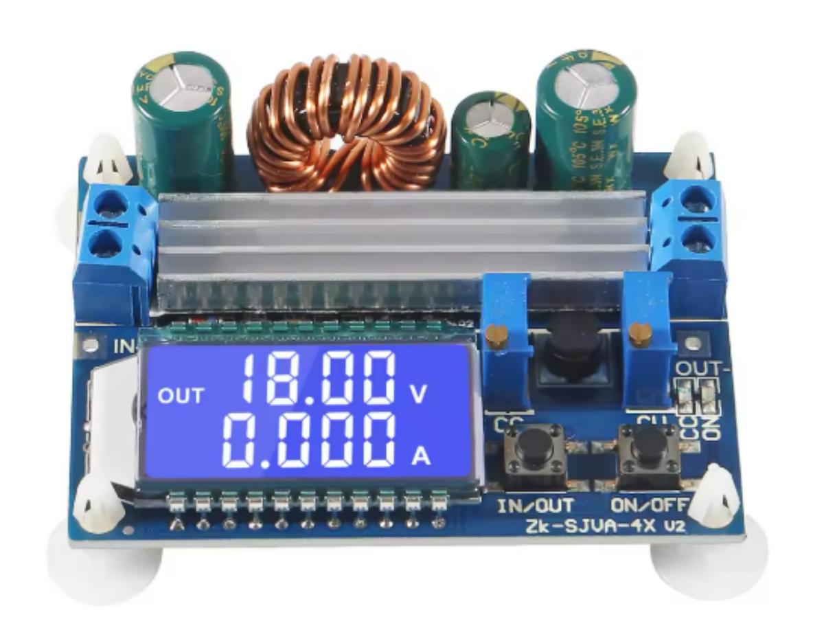
Buck-boost power supplies are widely used in the electronics field, and there are even dedicated power supply engineers who handle related work. If you aspire to become an electronic development engineer in the future, you can start by learning with the following constant voltage and constant current (CV/CC) LCD digital display buck-boost power module. It not only features digital displays for voltage and current but also allows you to adjust the output voltage and current. Now, let’s take a look at the essential hardware knowledge included in this module.
Reverse Polarity Protection
The input terminal of this module is equipped with reverse polarity protection. Even if you accidentally reverse the power connection, the module won’t burn out. The simplest solution is to use a unidirectionally conducting diode—this is probably the first thing that comes to mind.
When the power is reversed, the diode cuts off the current, preventing a closed circuit from forming. However, diodes have a voltage drop, which causes power loss. To improve product quality—especially for devices with high power consumption requirements, such as low-power battery-powered products that demand long battery life—ordinary diodes are generally not used. For products with less strict power consumption needs, Schottky diodes (which have a lower voltage drop) are a viable option.
It’s worth noting that you can use diodes to build a circuit that works regardless of whether the power is connected positively or negatively, though this module we’re learning about doesn’t have this function. This is called a rectifier bridge circuit (full-bridge reverse polarity protection), and it looks like the diagram below. When Input 1 is connected to positive and Input 2 to negative, D3 and D6 conduct, allowing the output of positive and negative power (VCC and GND). When the connections are reversed, D4 and D5 conduct instead, still providing the correct VCC and GND output. However, the drawback is obvious: whether connected correctly or reversed, two diodes will produce voltage drop losses—twice the loss of the simple single-diode reverse polarity protection circuit.

So what do products requiring low power consumption and long battery life use? That’s right—MOSFETs. The on-resistance voltage drop across a MOSFET is relatively small, so according to the formula P=UI, the resulting power loss is also minimal. It leverages the switching characteristics of MOSFETs to control the circuit’s conduction and cutoff. NMOS is used in low-side series connection—you can simply understand this as being connected to the ground side; PMOS, on the other hand, is used in high-side series connection, meaning it’s connected to the VCC side.

In an NMOS transistor circuit, when connected correctly, the voltage Vgs between the Gate (G, pin 1) and Source (S, pin 2) will exceed the threshold voltage Vth, allowing the Drain (D) and Source (S) of the MOSFET to conduct. When the power is reversed, the MOSFET will cut off.

When an PMOS transistor is connected correctly, its gate (G) is at 0V, which turns the PMOS on. The current flowing from the Drain (D) to the Source (S) then shorts the parasitic diode.
Backflow Prevention
The output terminal of this module is also equipped with backflow prevention, eliminating the need for an additional backflow prevention diode when charging batteries. As the name suggests, backflow refers to current flowing back from the load to the power supply, which can damage the power source. There are generally two scenarios that cause backflow.
One is when the load is an inductive load or a battery—during operation, it generates an induced electromotive force, which flows back to the power supply’s output terminal. The other is when switching between different voltage levels, where high voltage may flow back to the low-voltage side.
Similar to reverse polarity protection, the unidirectional conduction characteristic of diodes can solve this problem, as can MOSFETs and transistors. The diagram below shows a dual-MOSFET backflow prevention circuit.
When powered on normally, the gate-source voltage meets the conduction requirement, so the PMOS transistor turns on and power supply operates normally. If the input voltage suddenly drops out, the MOSFET will cut off, preventing backflow.

There’s also the transistor-based backflow prevention circuit. When connected correctly, the transistor turns on through resistor voltage division. When reversed, the transistor cuts off, effectively preventing backflow.

CV/CC
In daily use, you may come across CV and CC, which stand for Constant Voltage and Constant Current respectively. Constant Voltage means the power supply automatically adjusts the output current to maintain a stable output voltage. Similarly, Constant Current mode refers to the power supply automatically regulating the output voltage to keep the current steady. Both modes ensure that the device operates stably, safely and reliably under various environmental conditions.

For example, in this Zener diode constant current circuit, when Zener diode D1 operates in the reverse breakdown region, the voltage across it stabilizes at its nominal Zener voltage UZ. At this point, the base voltage VB of transistor Q1 is clamped at UZ, remaining constant. Obviously, the voltage across R3 is stabilized at UZ minus the forward voltage drop between the transistor’s base and emitter (0.7V). According to Ohm’s Law, the current through R3 remains unchanged.
Similarly, if we replace diode D1 in this circuit with a transistor, the voltage across R3 will also be fixed due to the characteristics of this transistor, so the current will naturally stay constant.
Of course, op-amps with voltage follower characteristics can also achieve constant current. As shown in the diagram below, the voltages at the op-amp’s input pins 2 and 3 are equal (a result of the virtual short characteristic). At this point, the voltage across R2 is equal to Vin—regardless of changes in VCC and load R3, the current flowing through R2 remains constant.

Next is this constant voltage circuit. When the diode conducts, it provides a stable reference voltage that fixes the base voltage of the transistor. At this point, the output voltage OUT remains constant. Here, D3 is used for temperature compensation, ensuring that D4’s performance stays stable regardless of temperature changes.

Power Conversion
The most prominent metal coil on the front of this module is its energy storage inductor—the core component that enables the module’s buck and boost functions. In addition, there are diodes, MOSFETs, and filter capacitors. When the input voltage is lower than the target output, the module operates in Boost mode, where the inductor stores energy and then superimposes it on the input voltage.
When the MOSFET is on, the inductor accumulates energy; when the MOSFET turns off, the inductor releases this stored energy, which is then added to the input voltage—achieving voltage boosting.
For voltage bucking (step-down), the inductor limits the current before releasing energy, essentially reducing the high input voltage to a lower output voltage. This process also relies on the MOSFET’s switching action to control the energy storage inductor.
The MOSFET’s on-off state is regulated by a dedicated buck-boost controller IC. This chip receives control signals from an MCU or potentiometer, generates PWM (Pulse-Width Modulation) waveforms, and adjusts the MOSFET’s duty cycle to achieve precise voltage regulation.
Control and Sampling
Sampling is accomplished using resistors. When current flows through a resistor, a voltage drop is generated; alternatively, voltage divider resistors are used to step down the voltage. This voltage is then amplified by an operational amplifier (op-amp) before being fed into the MCU for control.
The MCU first collects the voltage/current signals and performs ADC (Analog-to-Digital Conversion) on them. Next, it processes key press commands to implement mode switching and on/off control, then drives the LCD to display voltage, current, and operating status. Finally, it outputs control signals to adjust the duty cycle of the power circuit.
The two blue components on the module are potentiometers—variable resistors that allow for manual adjustment of voltage and current.

Output Ripple
The module’s low output ripple is attributed to its built-in LC filter circuit. First, let’s clarify what ripple is: it refers to periodic fluctuations in the power supply’s output. Such fluctuations are generated both at the input terminal of switching power supplies and during their switching cycles—with the former being low-frequency ripple and the latter high-frequency ripple. Digital circuits are sensitive to power supply noise, which can cause logic errors and false triggers. RF/analog circuits, on the other hand, require extremely clean power to ensure optimal performance. Therefore, filtering is indispensable.
Typically, you can reduce ripple by increasing the inductance and output capacitance. This is because a larger inductor minimizes current fluctuations within it, while a larger capacitor suppresses output ripple more effectively. For this reason, a high-capacity electrolytic capacitor is often used, with a ceramic capacitor connected in parallel nearby to suppress high-frequency noise. If additional filtering is needed, an extra stage of LC filter can be added.
In addition, one of the most effective methods is LDO (Low-Dropout Regulator) filtering, though it comes with a higher cost. As a low-dropout linear regulator, the LDO filters out spurious high-frequency signals from the input power, allowing only the desired stable DC or low-frequency signals to pass through—ultimately delivering an ultra-low noise, high-stability output voltage. EMI (Electromagnetic Interference) filtering is another option: by connecting an inductor after the diode, it suppresses high-frequency noise effectively.
FAQ
What are the disadvantages of buck – boost converters?
The biggest drawback of buck-boost converters is the reversed output polarity relative to the input. For example, if the input power supply is positive, the output will be negative—careless wiring can lead to reverse connection and damage components.
Additionally, the ripple generated by the inductor is particularly noticeable. Moreover, the switching transistor must withstand the superposition of input and output voltages. For instance, when the input is 12V and the output is -12V, the switching transistor will momentarily bear a 24V voltage stress, making it prone to failure.
When to use a buck – boost?
You can use a buck-boost converter when you need flexible voltage step-up/step-down and can tolerate polarity inversion.
Which is better, buck – boost or Sepic converter?
The Sepic converter offers the advantage of maintaining the same input and output polarity (e.g., a 5V input yields a 10V positive output) and lower ripple, but it features a more complex circuit with more components and higher cost. In contrast, the buck-boost converter has a simple structure, fewer components, and lower cost, but it reverses the output polarity and produces larger ripple.
Is constant current AC or DC?
Constant current can be achieved for both AC and DC, but DC constant current is more common in daily applications. For example, the constant current fast charging of mobile phones uses DC with a stable current; AC constant current also exists (such as AC constant current sources for motor testing), but it is rarely encountered in daily life.
Why do LEDs need constant current?
LEDs are highly sensitive to current fluctuations: slightly excessive current can cause them to overheat, gradually dim, or even burn out immediately. Furthermore, the voltage of LEDs varies with temperature—if the voltage is forced to remain constant, the current will fluctuate randomly, leading to flickering brightness.
What happens when the voltage is constant?
According to Ohm’s Law (I=U/R), the current will inevitably change when the load resistance varies. For example, replacing a light bulb with a brighter one (higher wattage, lower resistance) in a home with a constant 220V voltage will increase the current and consequently the power. If the load is short-circuited, the current will surge drastically. Therefore, the power supply must be equipped with overcurrent protection to prevent burnout.