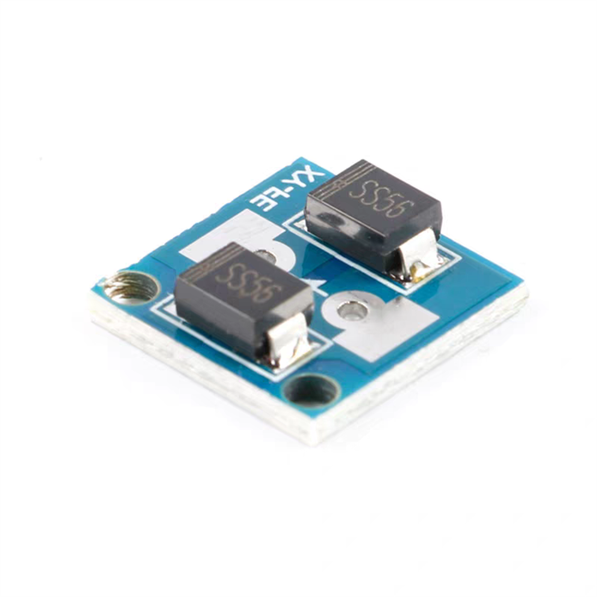
Reverse Polarity Protection Module
$0.971pcs
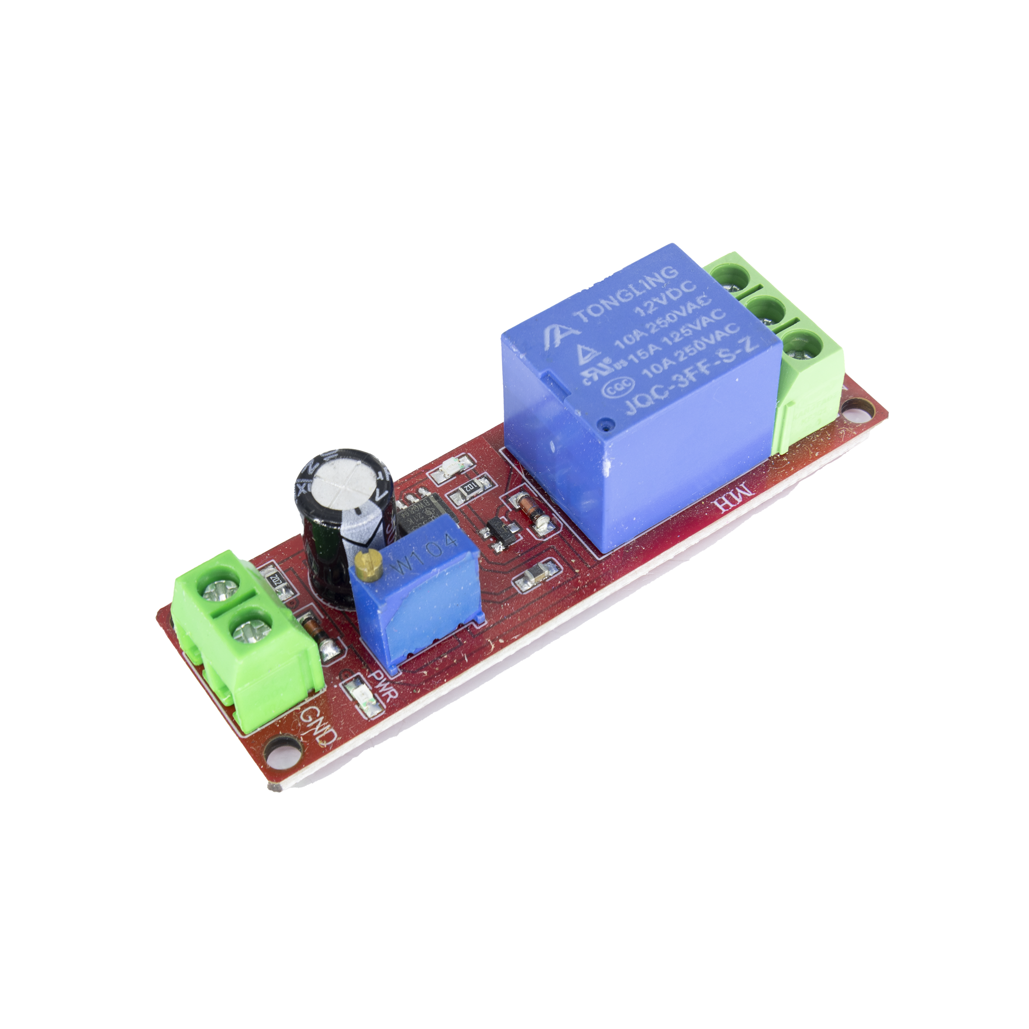
NE555 Time-Delay Relay Module
$3.001pcs


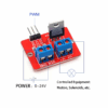
IRF520 MOSFET PWM Adjustment Module
$0.981pcs
The IRF520 driver module (MOSFET driver module) utilizes IRF520 power MOSFETs to deliver PWM-regulated output, making it suitable for controlling LED lighting and motors.
| Dimensions | 33.4 × 25.6 mm |
|---|---|
| Brand |
easyelecmodule |
3551 in stock


Reviews
There are no reviews yet.