Blog
Introducing RS485 and how to convert it to USB
What is RS485?

- Logic 1 is represented when line A is 2–6V higher than line B.
- Logic 0 is represented when line A is 2–6V lower than line B.
- A ground pin provides a voltage reference.
- There’s also an enable pin that controls the connection between the driver and the bus. When activated, the transmitter switches to a high-impedance state—it sends neither 1s nor 0s, acting as a “silent mode” on the bus to allow multiple devices to share the bus time-divisionally.
- A difference greater than +200mV outputs positive logic (corresponding to logic 1 from the transmitter).
- A difference less than -200mV outputs negative logic (corresponding to logic 0 from the transmitter).
- The receiver can recognize voltage differences ranging from 200mV to 6V.

- A daisy chain topology connects nodes in a series. Each node has two connection lines—one linking to the previous node and the other to the next. All devices are connected in parallel to a single bus, eliminating stub lines of varying lengths, and terminating resistors can be used at both ends.
- A bus topology connects all devices to a central cable called a bus. Devices are connected sequentially, with no stub lines of varying lengths, which helps maintain signal integrity.
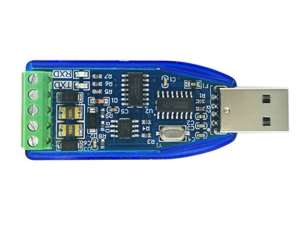
RS485 to USB

- GND: Common ground pin, directly connected to the USB bus ground.
- TXD: Serial data output.
- RXD: Serial data input, with built-in configurable pull-up and pull-down resistors.
- V3: For a 3.3V supply voltage, connect to VCC to input external power. For a 5V supply voltage, connect an external 0.1μF decoupling capacitor.
- UD+: USB signal, directly connected to the USB bus D+ data line (the chip has a built-in USB pull-up resistor).
- UD-: USB signal, directly connected to the USB bus D- data line.
- XI (Input): Crystal oscillator input pin, requiring an external 12MHz crystal and oscillation capacitors. This is because the CH340 chip needs an external 12MHz clock signal at the XI pin for normal operation. Typically, the clock signal is generated by the chip’s built-in inverter via crystal-stabilized oscillation. The peripheral circuit only needs a 12MHz crystal connected between the XI and XO pins, plus oscillation capacitors connected from XI and XO to ground respectively. However, the CH340G used here does not have a built-in inverter—an external inverter is required, which we will explain in detail later.
- XO (Output): Crystal oscillator output pin, requiring an external 12MHz crystal and oscillation capacitors.
- CTS# (Input): Modem control input signal (Clear to Send), active low (high).
- DSR# (Input): Modem control input signal (Data Set Ready), active low (high).
- RI# (Input): Modem control input signal (Ring Indicator), active low (high).
- DCD# (Input): Modem control input signal (Data Carrier Detect), active low (high).
- DTR# (Output): Modem control output signal (Data Terminal Ready), active low (high).
- RTS# (Output): Modem control output signal (Request to Send), active low (high).
- R232 (Input): Auxiliary RS232 enable, active high with a built-in pull-down resistor.
- VCC: Positive power supply input pin, requiring an external 0.1μF power decoupling capacitor.
CH340G Schematic Diagram:


FAQ
1. What is RS485 used for?
It’s mainly used in industrial scenarios—for example, connecting devices like PLCs, sensors, and inverters to transmit data stably over long distances. It’s also employed in access control and monitoring system communications, remote meter reading (for electricity and water meters), as well as signal transmission for security cameras and alarm devices.
2. Is RS485 2 wire or 4 wire?
The most common type is 2-wire, which only allows data reception or transmission at a time and saves on wiring costs. The 4-wire type enables simultaneous reception and transmission but is less used due to more complex wiring.
3. Is RS485 the same as Ethernet?
No, they are completely different communication methods. RS485 supports long-distance transmission (up to 1200 meters) but has moderate speed (max 10Mbps), making it suitable for point-to-point or multi-point connections between a few devices. Ethernet is used for local area networks (LANs), with a maximum transmission distance of 100 meters over twisted pair, and offers high speeds (100Mbps, 1Gbps, etc.), making it better for star topology networks.
4. Is RS485 analog or digital?
RS485 is a digital communication standard. It transmits discrete digital signals, using differential voltage to represent high and low levels.
5. What is RS485?
It’s a differential serial communication standard specifically designed for complex industrial environments. It enables reliable long-distance data transmission between multiple devices and is widely used in industrial settings.
6. What is RS485 cable?
An RS485 cable is a dedicated cable for this standard, typically shielded twisted pair (STP) to reduce electromagnetic interference. It has a characteristic impedance of 120Ω to avoid signal reflection. The 2-wire type uses one pair of twisted wires, while the 4-wire type requires two pairs.
7. How to convert RS485 to USB?
You can use an RS485-to-USB converter, which contains specialized chips (such as MAX485 and CH340). Wiring is simple: connect the A and B terminals of the RS485 device to the corresponding A and B terminals of the converter, then plug the converter’s USB port into a computer.
8. Is an RS485 to USB converter easy to install?
It’s extremely easy to install. For hardware, just connect the wires—some terminals can be fixed with screws, no soldering required. For software, install the corresponding driver (e.g., CH340 driver), and the computer will automatically recognize the port. Even beginners can handle it.
9. How do I connect my RS485 to my computer?
First, prepare an RS485-to-USB converter. When wiring, connect the A terminal of the RS485 device to the A terminal of the converter, the B terminal to the B terminal, and optionally connect GND to enhance stability. Then install the driver, find the recognized serial port in the computer’s Device Manager, and finally use a serial port assistant to set parameters like baud rate and data bits to enable communication.
10. What is CH340?
CH340 is a USB-to-serial chip produced by Chinese manufacturers. It’s affordable and commonly used in low-cost serial devices such as RS485 converters and Arduino development boards. Its main function is to convert USB signals into TTL serial signals.
11. CP2102 vs CH340?
CP2102, made by Silicon Labs, is a mid-to-high-end chip with better stability, suitable for industrial scenarios. It’s more expensive, natively supported by most systems, and often used in industrial equipment and high-end development boards. CH340 is a low-cost Chinese chip, sufficient for daily use or general industrial scenarios. It requires driver installation (manual adaptation for some older systems) and is mostly used in consumer devices and entry-level development boards.
12. What is the CH340 driver for?
The CH340 driver is software that allows computers to recognize the CH340 chip. After installation, the computer will recognize the CH340 device as a virtual serial port (e.g., COM port), enabling data transmission between the computer’s USB port and serial devices like RS485. It supports systems such as Windows and Linux, with no additional settings needed after installation.