
battery-management-systems-BMS-relay-21~30S
$84.091pcs
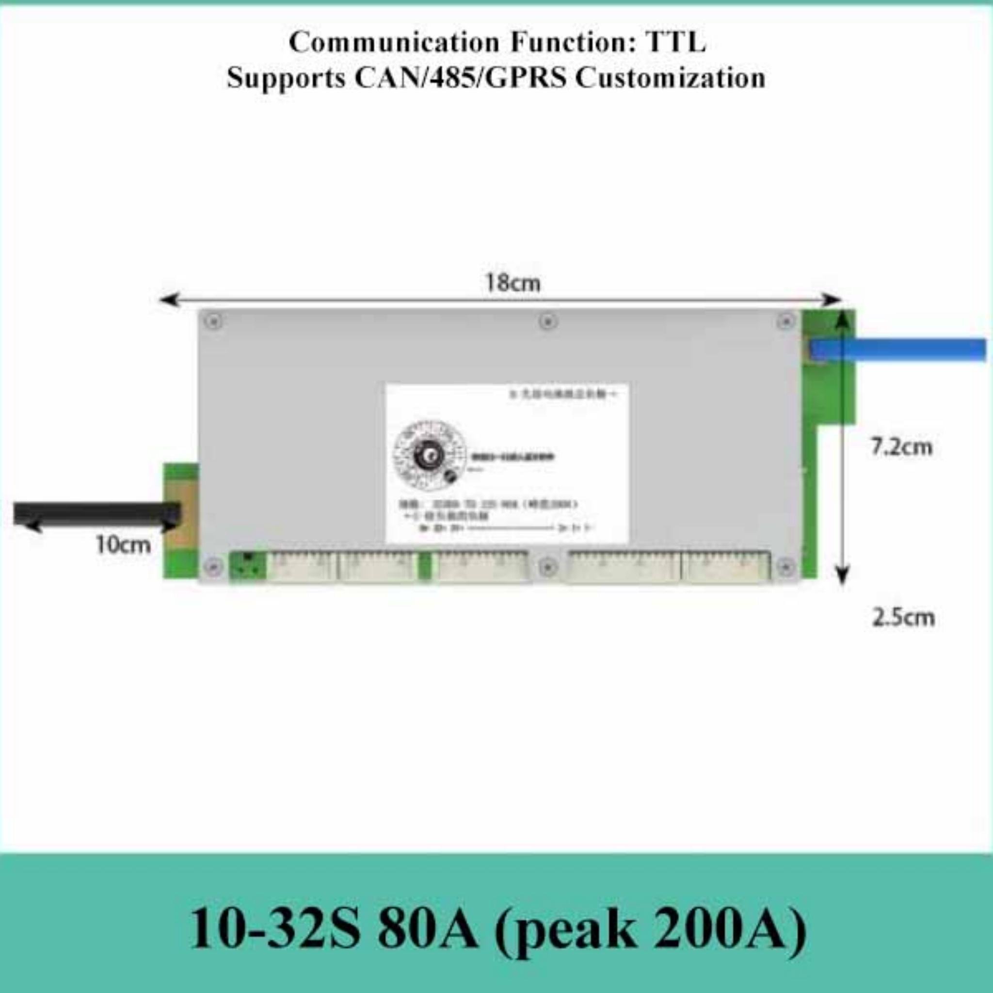
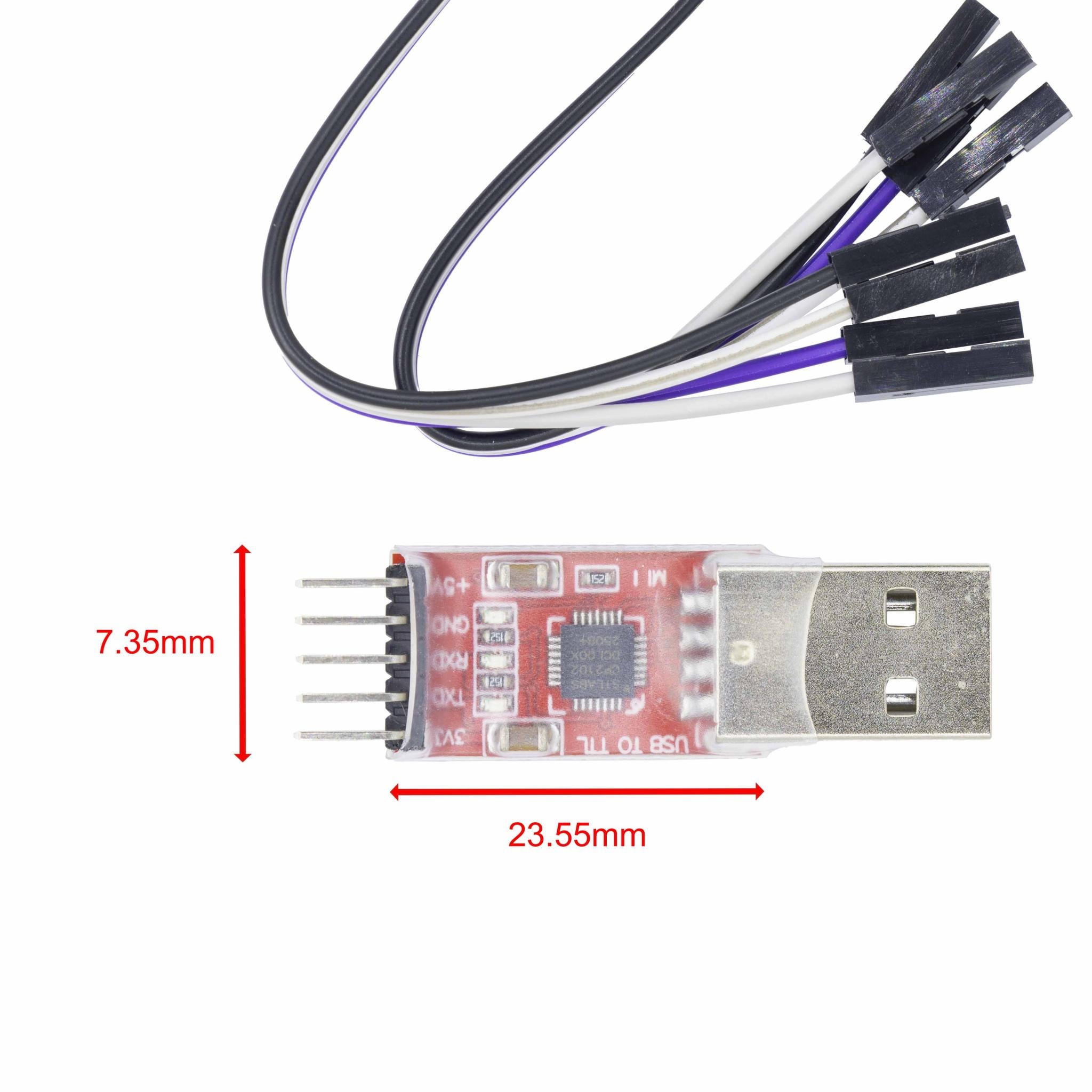
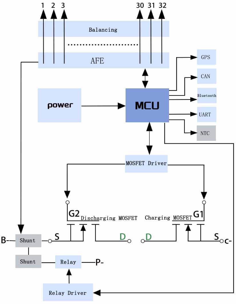
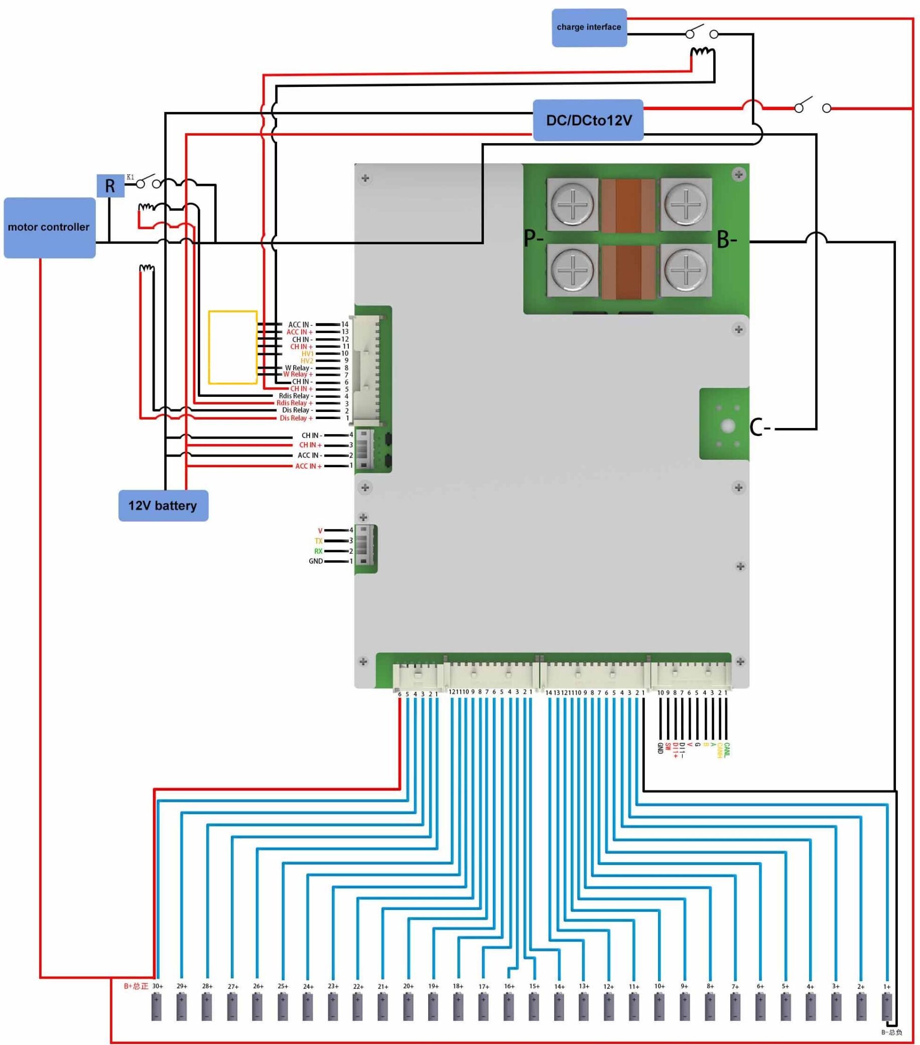
The 400A intelligent relay BMS: real-time monitoring (cell voltage, temperature, high-voltage), battery balancing (cell consistency), customizable CAN/485/TTL communication.
| Dimensions | 145 × 110 × 170 mm |
|---|---|
| Brand |
easyelecmodule |
2007 in stock


Related products

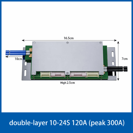
battery-management-systems-BMS-10~24S
key functions include: single-cell voltage detection, temperature detection, high-voltage detection, battery balancing control, support for CAN/485/TTL communication protocols, Bluetooth (for mobile app connectivity), sleep/wake-up control, delayed power-off function, State of Charge (SOC) estimation, and MOSFET control.


Battery-management-systems-BMS-4S
The 4S-BMS-MM32L073 models are all-in-one Battery Management Systems (BMS). Their key functions include: single-cell voltage detection, temperature detection, high-voltage detection, battery balancing control, support for CAN/485/TTL communication protocols, Bluetooth (for mobile app connectivity), sleep/wake-up control, delayed power-off function, State of Charge (SOC) estimation, and MOSFET control.


Reviews
There are no reviews yet.