Blog
How to use LM75 temperature sensor with Arduino?
How to use LM75 sensor?
Let’s just get straight to how it’s done, starting with the wiring. Follow these steps exactly, and you’re sure to build a temperature alarm with real-time display.
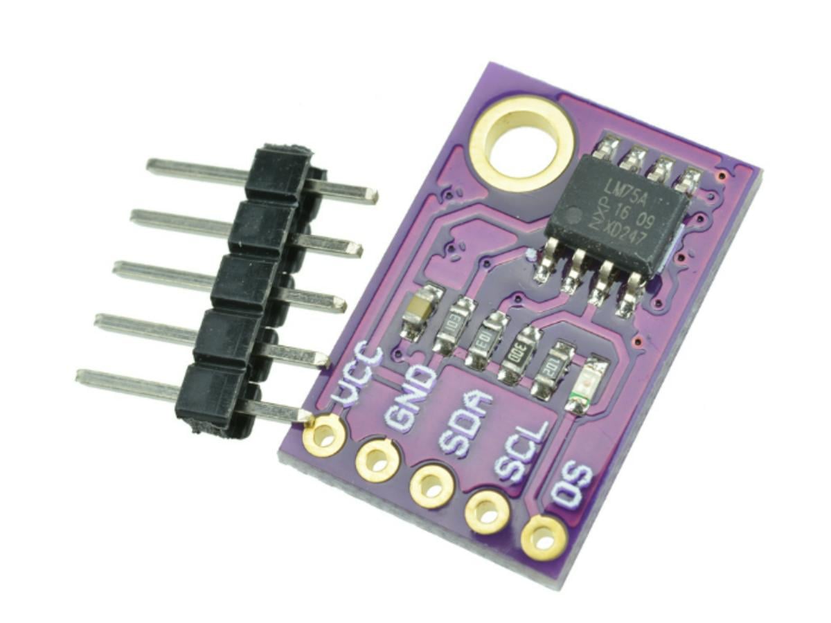
- Connect the VCC pin of the LM75 to the 5V pin of the Arduino Uno.
- Connect the GND pin of the LM75 to the GND pin of the Arduino Uno to ensure a common ground.
- Connect the SDA pin of the LM75 to the A4 pin of the Arduino Uno (the I2C data pin).
- Connect the SCL pin of the LM75 to the A5 pin of the Arduino Uno (the I2C clock pin).
- Connect the OS pin of the LM75 to the D2 pin of the Arduino Uno (the on-board LED will light up for alarm).
- Connect the VCC pin of the LCD to the 5V pin of the Arduino Uno.
- Connect the GND pin of the LCD to the GND pin of the Arduino Uno.
- Share the SDA pin of the LCD with the SDA pin of the LM75, and connect them to the A4 pin of the Arduino Uno.
- Share the SCL pin of the LCD with the SCL pin of the LM75, and connect them to the A5 pin of the Arduino Uno.
- Connect the I/O control pin of the buzzer to the digital pin D3 of the Arduino Uno, the VCC pin to 5V, and the GND pin to ground.
CODE
					#include <Wire.h>
#include <LiquidCrystal_I2C.h>
const int LM75_ADDRESS = 0x48;
const int LED_PIN = 2;
const int BUZZER_PIN = 3;
const float ALARM_TEMP = 45.0;
const float HYSTERESIS_TEMP = 44.875;
const float ERR_TEMP = -99.9;
float lastValidTemp = 25.0;
#define TEMP_REG    0x00
LiquidCrystal_I2C lcd(0x27, 16, 2);
void setup() {
  Wire.begin();
  Serial.begin(9600);
  pinMode(LED_PIN, OUTPUT);
  pinMode(BUZZER_PIN, OUTPUT);
  lcd.init();
  lcd.backlight();
  lcd.print("Temp: 25.0 C");
  digitalWrite(BUZZER_PIN, HIGH);
}

void loop() {
  float currentTemp = readLM75Temperature();
  static bool lastAlarm = false;
  if (currentTemp != ERR_TEMP) {
    lastValidTemp = currentTemp;
  }
  if (lastValidTemp >= ALARM_TEMP) {
    lastAlarm = true;
    digitalWrite(LED_PIN, LOW);
    digitalWrite(BUZZER_PIN, LOW);
  } else if (lastValidTemp <= HYSTERESIS_TEMP) {
    lastAlarm = false;
digitalWrite(LED_PIN, HIGH);
digitalWrite(BUZZER_PIN, HIGH);
  }

  Serial.print("Temperature: ");
  Serial.print(lastValidTemp);
  Serial.println(" °C");
  if (currentTemp == ERR_TEMP) {
    Serial.println("--- I2C Error: use last valid temp ---");
  }
  lcd.setCursor(0, 0);
  lcd.print("Temperature:    ");
  lcd.setCursor(12, 0);
  lcd.print(lastValidTemp);
  lcd.setCursor(0, 1);
  if (lastAlarm) {
    lcd.print("ALARM! >45C    ");
  } else {
    lcd.print("Normal        ");
  }
  delay(1000);
}
float readLM75Temperature() {
  Wire.beginTransmission(LM75_ADDRESS);
  Wire.write(TEMP_REG);
  byte err = Wire.endTransmission();
  if (err != 0) {
    Serial.print("I2C Error: ");
    Serial.println(err);
    return ERR_TEMP;
  }
  Wire.requestFrom(LM75_ADDRESS, 2);
  if (Wire.available() != 2) {
    Serial.println("No Data");
    return ERR_TEMP;
  }
  byte highByte = Wire.read();
  byte lowByte = Wire.read();
  int16_t rawData = (highByte << 8) | lowByte;
  return (rawData >> 5) * 0.125;
}
Code introduction
We have set a hysteresis temperature (HYSTERESIS_TEMP) in the code to prevent the alarm from being frequently triggered and deactivated when the temperature fluctuates around 45°C. For example, after the alarm is triggered when the temperature rises to 45°C, it will only be deactivated when the temperature drops below 44.875°C, rather than stopping as soon as the temperature falls below 45°C.
ERR_TEMP in the code is a marker value for I2C communication failures. The normal measurement range of the LM75 is -55°C to 125°C, and -99.9°C is outside this range. You can use this value to distinguish between valid temperature readings and error states.
The overall operation flow of the entire code is as follows, and you can first get a general understanding of its logic: Initialize I2C, serial port, and peripherals, and display the initial temperature on the LCD; read the LM75 temperature every second and check if the communication is normal; control the LED/buzzer according to temperature thresholds (trigger at 45°C, deactivate at 44.875°C); output temperature and status via the serial port, and update temperature and alarm information on the LCD in real time; if communication fails, retain the last valid temperature and prompt an error via the serial port.

Now I will introduce this code in detail to help you understand it more clearly and thoroughly. First, two header files, Wire.h and LiquidCrystal_I2C.h, are included. Wire.h is Arduino’s built-in core library for I2C communication. Both the LM75 temperature sensor and the 1602 I2C LCD communicate with Arduino via the I2C bus, so this library must be included to implement the sending and receiving of I2C data. LiquidCrystal_I2C.h is a dedicated driver library for the 1602 LCD with an I2C interface. After including it, you no longer need to connect the traditional control pins such as RS, D4-D7 of the LCD. The LCD can be controlled only through the SDA and SCL pins, making both wiring and programming much simpler.
The constant const int LM75_ADDRESS = 0x48 defined in the code is used to specify the default I2C slave address of the LM75 sensor. The I2C address of the LM75 is determined by the voltage levels of its A0, A1, and A2 pins, and the address is 0x48 when all three pins are grounded. If you modify the hardware wiring to adjust the address, remember to update this constant synchronously.
const float ALARM_TEMP = 45.0 is the set alarm trigger threshold. when the detected temperature is ≥45°C, the LED and buzzer will be activated for alarm. float lastValidTemp = 25.0 is used to save the last valid temperature value, with an initial value set to 25°C. When I2C communication fails (such as the sensor being disconnected), the system will continue to use the last read temperature value to avoid abnormal data output that causes confusion in the alarm logic.

#define TEMP_REG 0x00 defines the address of the LM75 temperature data register. According to the LM75 datasheet, its register address is fixed at 0x00. You need to send an instruction to this address to read temperature data. In LiquidCrystal_I2C lcd (0x27, 16, 2), 0x27 is the common address of the 1602 I2C LCD, 16 indicates that the LCD has 16 columns, and 2 indicates 2 rows.
Serial.begin (9600) initializes serial communication with a baud rate set to 9600. Later, you can view temperature and error information through the serial monitor. Remember to ensure that the baud rate of the serial monitor is consistent with this value, otherwise garbled characters will appear.
pinMode (LED_PIN, OUTPUT) and pinMode (BUZZER_PIN, OUTPUT) set the LED and buzzer control pins to output mode. Arduino’s digital pins are input mode by default, and you must manually set them to output to drive external peripherals.
lcd.init () initializes the LCD display and completes the initialization of I2C communication internally. Immediately after, lcd.backlight () is executed to turn on the LCD backlight, because the backlight is turned off by default after LCD initialization and needs to be manually turned on for normal display.

In the loop infinite loop program, the code first executes float currentTemp = readLM75Temperature (). This calls the custom temperature reading function to obtain the current temperature detected by the LM75 and assign it to currentTemp. static bool lastAlarm = false declares a static boolean variable to save the last alarm state. The static keyword makes the variable initialized only when entering loop () for the first time (with a value of false), and retains the last state in subsequent loops, which is the key to implementing the alarm hysteresis logic.
When the temperature is between 44.875°C and 45°C, lastAlarm maintains its original state to avoid frequent switching of the alarm. if (currentTemp != ERR_TEMP) is used to judge whether the temperature reading is valid. If valid, update lastValidTemp to currentTemp; if invalid, use the previous valid temperature value.
Alarm logic judgment: If lastValidTemp ≥ ALARM_TEMP (≥45°C), set lastAlarm to true, and execute digitalWrite (LED_PIN, LOW) and digitalWrite (BUZZER_PIN, LOW) at the same time to turn on the LED and make the buzzer sound continuously; if lastValidTemp ≤ HYSTERESIS_TEMP (≤44.875°C), set lastAlarm to false, execute digitalWrite (LED_PIN, HIGH) and digitalWrite (BUZZER_PIN, HIGH) to turn off the LED and buzzer. Serial output prints lastValidTemp to the serial monitor through Serial.print series statements. When currentTemp is ERR_TEMP, additionally print “I2C Error: use last valid temp ” to prompt a communication error.
LCD display: Execute lcd.setCursor (0, 0) to position the LCD cursor at column 0, row 0, then execute lcd.print (“Temperature:”) to print the string and add spaces; execute lcd.setCursor (12, 0) to position the cursor at column 12, row 0, and print lastValidTemp to display the current temperature; execute lcd.setCursor (0, 1) to position the cursor at column 0, row 1, and print “ALARM! >45C ” if lastAlarm is true, or “Normal ” if false. delay (1000) makes the main loop execute once every 1 second to control the refresh rate of temperature reading and display.

Next, let’s introduce the readLM75Temperature () temperature reading function. This is a custom function that allows reading the temperature data detected by the LM75 and converting it into an actual value. Wire.beginTransmission (LM75_ADDRESS) specifies the slave address as LM75_ADDRESS and initiates I2C communication with the LM75; Wire.write (TEMP_REG) sends the address of the register to be read (temperature register 0x00) to the LM75, telling the LM75 to return the data of this register; byte err = Wire.endTransmission () ends the I2C transmission and obtains an error code, where 0 means the transmission is successful, and a non-zero value means communication failure (such as the sensor not responding).
If err≠0, print the error code through the serial port and return ERR_TEMP (-99.9) to mark a reading failure; after successful transmission, execute Wire.requestFrom (LM75_ADDRESS, 2) to request reading 2 bytes of data from the LM75; execute if (Wire.available () != 2) to judge whether 2 bytes are read, and if not, print “No Data” and return ERR_TEMP.
Through the above series of steps, the temperature data can be read successfully, but the current data is in a form different from the usual digital temperature and is inconvenient for us to use, so data parsing is also required. byte highByte = Wire.read () and byte lowByte = Wire.read () read the high and low bytes of the temperature data respectively; int16_t rawData = (highByte << 8) | lowByte shifts the high byte left by 8 bits and performs a bitwise OR with the low byte to combine into a complete 16-bit signed integer to avoid data overflow;
return (rawData >> 5) * 0.125 can convert the data into the actual temperature. Among the 16-bit data of the LM75, only the first 11 bits are valid (bit 15 is the sign bit, bits 14~5 are the integer part, and bits 4~0 are the fractional part), so shifting right by 5 bits discards the invalid bits. Multiplying by 0.125 is because the temperature resolution of the LM75 is 0.125°C (1/8°C), and finally you can get the actual temperature value.

FAQ
What does the temperature sensor do?
A temperature sensor can detect temperature changes in the environment and objects, converting the physical quantity of temperature into electrical signals such as voltage, current, and digital signals. It is indispensable for industrial temperature control, smart home devices, and Arduino-based temperature monitoring projects alike.
What are the 4 types of temperature sensors?
- NTC temperature sensors: These rely on the change in resistance of a negative temperature coefficient thermistor with temperature to achieve temperature measurement.
- PT100 temperature sensors: These complete temperature detection based on the resistance change of a precision platinum resistor.
- Digital temperature sensors: These are devices that output digital signals directly, such as the DS18B20 and LM75 sensors.
- Analog temperature sensor integrated circuits: These are chips that output analog voltage signals linearly related to temperature, such as the LM35 temperature sensor.
What is the difference between LM35A and LM35D?
They differ in temperature measurement range and accuracy specifications. The LM35A has a wider range and higher accuracy, making it suitable for demanding industrial environments. The LM35D, on the other hand, is ideal for general-purpose applications.
Is LM35 affected by lightning?
Yes, it can be affected by lightning strikes. As a low-power analog temperature sensor integrated circuit, it does not have a built-in protection structure against high-voltage surges. The high-voltage spike pulses generated by lightning can conduct through the circuit to the sensor’s internal components, damaging the core elements and causing permanent failure. Not only the LM35, but also precision temperature sensor integrated circuits such as the LM75 IC and LM75A are susceptible to damage from lightning-induced surges if no lightning protection circuit is installed.
How much power does a LM35 consume?
Its operating current is typically only a few microamps to several milliamps, with corresponding power consumption ranging from microwatts to milliwatts. For this reason, it is particularly well-suited for battery-powered, low-power devices.
What are the common problems with the LM35?
There are quite a few common issues, including: Inaccurate temperature readings caused by poor circuit grounding or electromagnetic interference. Damage to the sensor integrated circuit due to reverse polarity connection when wiring it into a circuit. Unstable or even invalid output signals when used in environments that exceed its rated temperature range. Communication conflicts caused by improper I2C address configuration of the LM75 (when used together in a circuit).