Blog
The NE555 chip is used to design a pulse square wave signal generator with an adjustable duty cycle.

Introduction
The NE555 timer IC is a legendary component in electronics, beloved for its versatility, affordability, and ease of use. Whether you are a beginner testing your first circuit or a hobbyist building a custom project, this 8-pin chip delivers reliable timing and pulse-generation capabilities. This guide dives into its core specs, practical applications, comparisons to similar variants, and answers to common questions—all tailored to help you get the most out of the NE555.
What is the NE555?
The NE555 is a precision timing integrated circuit (IC) designed for generating time delays, oscillating signals, and pulse-width modulation (PWM). Introduced decades ago, it remains a staple in electronics because it combines analog and digital functionality: it uses two voltage comparators, an SR flip-flop, and a discharge transistor to operate in three key modes (astable, monostable, bistable).
Its enduring popularity stems from:
- Low cost (typically $0.08–$0.59 per unit)
- Wide voltage compatibility (works with 4.5V–15V, perfect for batteries or USB power)
- High output current (up to 200mA, enough to drive LEDs, buzzers, or small relays directly)
- Minimal external components (only resistors and capacitors needed for most circuits)

How does NE555 work?
NE555 is a commonly used integrated circuit, also known as the 555 timer. It can be used to generate various types of pulse waveforms, including square waves, pulses, sine waves, and so on. Its working principle is based on a timing circuit composed of internal comparators and various external components such as resistors and capacitors. NE555 typically consists of pins for supply voltage Vcc, ground GND, control voltage CV, output OUT, and reset RST.
The working principle of the NE555 is as follows: When the supply voltage Vcc is turned on, the circuit starts to operate, and the capacitor C begins to charge until its voltage reaches 2/3 of Vcc. At this point, the output of the internal comparator will become a high level, and the output OUT will also change from a low level to a high level. When the voltage of capacitor C drops to 1/3 of Vcc, the output of the internal comparator will become a low level, and at this time, the output OUT will also change from a high level to a low level. Capacitor C starts charging again, and the circuit begins a new cycle.
The period T (in seconds) is determined by the values of the external capacitor C and two external resistors R1 and R2. The formula is T = 0.693×(R1 + 2×R2)×C. The duty cycle D refers to the time proportion of the high level in the square wave period, and the formula is D = (R1 + R2)/(R1 + 2×R2). Therefore, by changing the values of capacitor C and resistors R1 and R2, the period and duty cycle of the square wave waveform can be changed.
In summary, the working principle of the NE555 is based on the construction of a timing circuit. By changing the values of external capacitors and resistors, the period and duty cycle can be controlled, thereby generating various pulse waveforms.

NE555 Key Specifications
Below are critical electrical and physical parameters extracted from the NE555 datasheet. These specs define the chip’s limits and help you avoid damage or performance issues.
| Parameter | Value |
|---|---|
| Supply Voltage | 4.5V – 15V |
| Output Current | ±200mA (max) |
| Maximum Supply Voltage (Vcc) | 16V |
| Maximum Power Dissipation (PD) | 600mW |
| Maximum Junction Temperature (TJ) | +125°C |
| Operating Temperature Range | 0°C – 70°C |
| Storage Temperature Range | -40°C to +150°C |
| Timing Error | ±5% (typical) |
NE555 Pin Configuration and Functions

| CONT | 5 | 12 | Input/output | Controls comparator thresholds, Outputs 2/3 × VCC, allows bypass capacitor connection |
| DISCH | 7 | 17 | Output | Open collector output to discharge timing capacitor |
| GND | 1 | 2 | — | Ground |
| OUT | 3 | 7 | Output | High current timer output signal |
| RESET | 4 | 10 | Input | Active low reset input forces output and discharge low. |
| THRES | 6 | 15 | Input | End of timing input. THRES > CONT sets output low and discharge low |
| TRIG | 2 | 5 | Input | Start of timing input. TRIG < ½ CONT sets output high and discharge open |
| VCC | 8 | 20 | — | Input supply voltage, 4.5V to 16V. SE555 maximum is 18V. |
NE555 vs LM555 Comparison Table
| Parameter | NE555 | LM555 |
|---|---|---|
| Manufacturer | Multiple (generic) | Texas Instruments |
| Operating Voltage Range | 4.5V – 15V | 4.5V – 15V (tighter voltage tolerance) |
| Max Output Current | ±200mA | ±200mA (more consistent under load) |
| Quiescent Current | ~10mA (at 5V) | ~10mA (similar, but with better stability) |
| Timing Error | ±5% (typical) | ±1% – ±2% (improved precision) |
| Operating Temperature Range | 0°C – 70°C (commercial grade) | -40°C – 85°C (industrial grade available) |
| Noise Immunity | Moderate (prone to power supply noise) | Better (tighter component tolerances) |
| Cost | Lower (≈$0.08 – $0.59) | Slightly higher (≈$0.10 – $0.65) |
| Best For | Hobby projects, basic timers, low-cost builds | Industrial controls, precision timing, harsh environments |
NE555 vs TLC555 Comparison Table
| Parameter | NE555 | TLC555 |
|---|---|---|
| Technology | Bipolar transistor | CMOS (low-power) |
| Operating Voltage Range | 4.5V – 15V | 2V – 18V (wider range for low/high voltage) |
| Max Output Current | ±200mA | ±100mA (lower, may need buffers for heavy loads) |
| Quiescent Current | ~10mA (at 5V) | ~25µA (at 5V) – 1/400th of NE555 |
| Timing Error | ±5% (typical) | ±2% – ±3% (good for low-power apps) |
| Operating Temperature Range | 0°C – 70°C (commercial grade) | -40°C – 85°C (industrial grade) |
| Input Impedance | Low (loads input sources) | High (no significant loading) |
| Noise Immunity | Moderate | Excellent (less susceptible to interference) |
| ESD Sensitivity | Low (robust to handling) | High (needs ESD precautions during handling) |
| Cost | Lower (≈$0.08 – $0.59) | Slightly higher (≈$0.12 – $0.70) |
| Best For | General projects, direct load driving | Battery-powered devices, low-power sensors, high-noise environments |
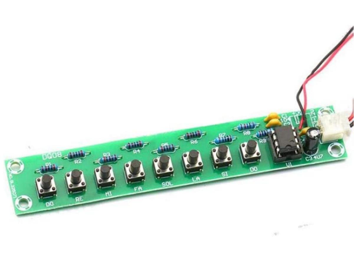
Example:NE555 pulse generator experiment
1.Experimental Software And Hardware
- Keil μVision4
- PZISP automatic download software
- HC6800S development board
2.Experimental Principle
The internal structure of the NE555 can be equivalent to a combination of multiple unit circuits, including 23 transistor triodes, 17 resistors, two diodes, a comparator, and an RS flip – flop. Notably, three high – precision 5kΩ resistors form a resistor divider, which provides reference voltages for the upper and lower comparators. That’s why it’s called “555”.
NE555 Pin Diagram
1->Ground (GND)
2->Trigger
3->Output
4->Reset
5->Control Voltage
6->Threshold
7->Discharge
8->Power Supply Voltage (Vcc)

A multivibrator is made up of a 555 timer and external components R1, R2, and C. Pin 2 and Pin 6 are directly connected. The circuit has no stable state but only two temporary stable states, and there’s no need for an external trigger signal. The power supply charges C through R1 and R2, and C discharges to the discharge terminal Dc through R2, making the circuit generate oscillations. Capacitor C charges and discharges between 2/3 Vcc and 1/3 Vcc, so a series of rectangular waves are generated at the output terminal, and the corresponding waveform is as shown in the diagram.
3.Experimental Step
- Connect the relevant experimental module circuits Experimental interface
- Write the pulse generator program Programming idea: Adjust the potentiometer to change the resistance value. The period of the pulses generated by the 555 timer will change accordingly, and the natural frequency will also change. By programming to record the number of pulses within 1 second, we can get the frequency. We need to use a timer for 1-second timing and a counter for pulse counting. Then, split the frequency into digits and display them on the LCD1602 screen.
- Download the pulse generator program Program download interface
- Debug and verify the experimental effect Adjust the potentiometer, and the corresponding frequency will be displayed on the LCD screen. The display effect is clear, and the response speed is relatively fast.
4.Experimental Code
					#include<reg51.h>
#include"lcd.h"

#define uchar unsigned char
#define uint  unsigned int
#define ulong   unsigned long
uchar code EN_CHAR1[16]={"   CYMOMETER    "};
uchar code EN_CHAR2[16]={"FREQ:         HZ"};
ulong Freq, TimeCount;
void main()
{
    uchar i, freqValue[6];
    LcdInit();
    TMOD=0x51;
    //Set timer for 50ms when using a 12MHz crystal oscillator
    TH0=0x3C;
    TL0=0xB0;
    //Enable interrupts
    ET0=1;ET1=1;EA=1;
    //Start timers
    TR0=1;TR1=1;
    for(i=0;i<16;i++)//Display on first line
    {
        LcdWriteData(EN_CHAR1[i]);
    }
    LcdWriteCom(0xc0);//Switch to second line for display
    for(i=0;i<16;i++)
    {
        LcdWriteData(EN_CHAR2[i]);
    }
    while(1)
    {
        if(TR0==0)         //When the counter stops, it indicates counting is complete
        {
            Freq = Freq + TL1;       //Read the value of TL
            Freq = Freq + (TH1 * 256); //Read the value of TH
            LcdWriteCom(0xc8);
            //Calculate the hundred thousands, ten thousands, thousands, hundreds, tens and units digits of the frequency
            freqValue[0]='0'+Freq%1000000/100000;
            freqValue[1]='0'+Freq%100000/10000;
            freqValue[2]='0'+Freq%10000/1000;
            freqValue[3]='0'+Freq%1000/100;
            freqValue[4]='0'+Freq%100/10;
            freqValue[5]='0'+Freq%10;
            for(i=0;i<5;i++)//Start from the highest digit
            {
                if(freqValue[i]==0x30)
                {
                    freqValue[i]=0x20;  //If it's 0, assign a space character
                }
                else
                {
                    break;
                }
            }
            for(i=0;i<6;i++)
            {
                LcdWriteData(freqValue[i]);
            }
            Freq=0;TH1=0; TL1=0;TR0=1; TR1=1;
        }
    }
}

void Timer0()   interrupt 1
{
    TimeCount++;
    if(TimeCount==20)//Timing reaches 1 second
    {
        TR0=0;
        TR1=0;
        TimeCount=0;
    }
    TH0=0x3C;
    TL0=0xB0;
}
void Timer1()   interrupt 3
{
    Freq=Freq+65536;
}
Applications
- Pulse-shaping circuits
- Missing-pulse detectors
- Pulse-width modulators
- Pulse-position modulators
- Sequential timers
- Pulse generators
- Frequency dividers
- Industrial controls
FAQS
Why is my NE555 circuit not oscillating (no output pulse)?
The most common issue is incorrect wiring of the RC network.
Can the NE555 drive a motor directly?
No—most small DC motors draw 300mA–1A, which exceeds the NE555’s 200mA max output current. Instead:
- Connect the NE555’s output (Pin 3) to the base of a transistor (e.g., TIP120).
- Connect the motor to the transistor’s collector and a separate power supply (matching the motor’s voltage).
- Add a flyback diode (1N4001) across the motor terminals to protect the circuit from voltage spikes.
How do I adjust the NE555’s duty cycle in astable mode?
Duty cycle (the percentage of time the output is “high”) is controlled by R₁ and R₂:
- To increase duty cycle (more “on” time): Increase R₁ or decrease R₂.
- To get a 50% duty cycle (equal “on/off” time): Set R₁ = R₂ (e.g., R₁=1kΩ, R₂=1kΩ, C=10µF—frequency ~60Hz).
- For variable duty cycle: Replace R₁ with a potentiometer (e.g., 10kΩ) and keep R₂ fixed (e.g., 1kΩ).
What’s the difference between the NE555 and the LMC555?
The LMC555 is a low-power variant of the NE555, designed for battery-powered projects. Key differences:
- Quiescent current: LMC555 uses ~10µA (vs. NE555’s ~10mA)—1000x less power.
- Voltage range: LMC555 works down to 1.5V (vs. NE555’s 4.5V), so it’s better for AA/AAA batteries.
- Tradeoff: The LMC555 has a lower max output current (±100mA) and higher cost (~$0.70 vs. NE555’s $0.08–$0.59).
How do I extend the NE555’s timing beyond 1 hour?
Using a single NE555 in monostable mode with a large capacitor (e.g., 1000µF) and resistor (e.g., 3.3MΩ) gives ~3.6 seconds of delay—too short for 1 hour. Instead:
- Cascade two NE555s: Use the first NE555 (monostable, 10-second delay) to trigger the second NE555 (monostable, 360-second delay). Combined, this gives 370 seconds (~6 minutes). For 1 hour, cascade 6 NE555s (each with 10-minute delays).
- Use a counter IC: Pair the NE555 (astable, 1Hz frequency) with a CD4060 counter. The CD4060 divides the frequency, so after 20 stages, you get a 1-hour pulse.