Blog
Use NE555 make an electronic keyboard
Music is everywhere. There is a wide variety of musical instruments, including string instruments and wind instruments. Some people can even play beautiful music with a single leaf or a rubber band. In fact, as long as the sound frequencies differ, the pitches will vary accordingly. Taking advantage of this principle, we can make a musical instrument ourselves using many interesting materials. For example, by filling glass bottles with different volumes of water, you can get bottles that produce different pitches. Prepare more of these bottles, and you will be able to tap out melodies of all kinds.
Speaking of frequency, does the term ring a bell? You may be more familiar with another word: Hertz (Hz). I believe you have seen this unit on the instruction manuals, packaging boxes, and specification sheets of many electrical appliances. It is the unit of frequency. Given this, it is only natural for us to associate that electronic components can also be used to make musical instruments.
Do you remember playing with an electronic keyboard piano when you were little? It looks a lot like a traditional piano, but is much smaller and cheaper. Plug it in, and you can pretend to be a pianist, playing any song you like. However, electronic keyboards are still relatively complex devices. We can start with the simplest and most basic aspects first—learning how to manipulate electronic components to produce the eight fundamental musical notes. If you develop further interest later, you can dig deeper and DIY your very own electronic organ!
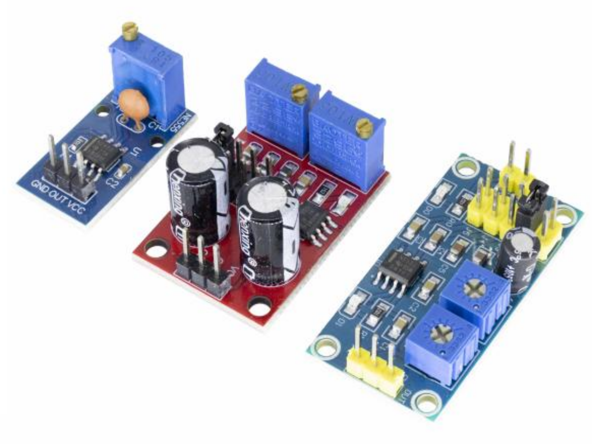
The electronic world cannot function without chips—chips are the brains of the electronic domain. To make a simple 8-tone electronic organ, the chip you will need is the NE555. Now, let us learn about it together.
NE555 Chip
As a matter of fact, this chip is not specifically developed for products like electronic organs. It boasts an extremely wide range of applications and is a highly practical timer chip, enjoying enduring popularity and brisk sales over the years.
The NE555 is a member of the 555 series chips. It features 8 pins and comes with functions such as timing control and pulse modulation. Based on an astable multivibrator circuit, it can output various waveforms including rectangular waves, triangular waves and square waves. In real life, the NE555 is often used in controllers, timers and tuners, and it is also applied in the blinking turn signals of automobiles.
Pinout Diagram and Functions of the NE555:

- VCC: Power supply;
- GND: Ground;
- CONT: Control pin, which adjusts frequency and duty cycle using an external capacitor;
- RESET: Reset pin, the chip stops working and resets when connected to ground;
- OUT: Output pin, outputs square wave signals;
- THRESH: Non-inverting input of the voltage comparator;
- TRIG: Inverting input of the voltage comparator;
- DISC: Amplifier power supply pin, connected to low-pass filter components.
- Parameters: Supply voltage 4.5–18V; Supply current 10–15mA; Output current 225mA (max); Rise/fall time 100 ns.
Astable Multivibrator
So, what exactly is the astable multivibrator circuit mentioned above? It generally falls into three types: astable, monostable, and bistable. The astable type requires no input signal to trigger oscillation, while the other two do. The output signal of the astable multivibrator is unstable in both of its states; the monostable multivibrator enters an unstable state once triggered, but returns to a stable state after a certain period; the bistable multivibrator switches from one stable state to another stable state.
The 555 timer is a highly classic and widely used integrated circuit (IC) version of the multivibrator. It adopts a more sophisticated design, which can address the issue of inaccurate timing that plagues ordinary multivibrators.
Lets now take a look at the relatively basic astable multivibrator.

This BJT astable multivibrator switches back and forth between two operating states.State 1: Q1 is conducting, and its collector voltage is close to 0V. At this time, C1 is charged by the currents through R2 and Q1. The base voltage of Q2 equals the voltage across C1, which rises gradually but does not reach 0.6V, so Q2 remains cut off. Meanwhile, C2 discharges through R3 and R4, and the output voltage is at a high level (since the voltage after C2 discharges is slightly lower than the supply voltage). This state persists until the base voltage of Q2 reaches 0.6V, after which Q2 turns on and the circuit switches to State 2.
State 2: When Q2 conducts, its collector voltage (i.e., the output) drops from high level to nearly 0V. C2 couples this voltage change to the base of Q1, causing Q1 to cut off instantaneously. After Q1 cuts off, its collector voltage rises to a high level. Then C1 discharges through R1 and R2, while C2 starts charging from 0V via the current through R3 until the voltage reaches 0.6V. The base voltage of Q1 equals the voltage across C2 and increases gradually as C2 charges. This state continues until the base voltage of Q1 hits 0.6V, after which Q1 turns on again and the circuit reverts to State 1.
Astable Multivibrator Circuit with NE555
Now let us move on to learn about the astable multivibrator circuit constructed with the NE555 chip. Here is its schematic diagram.

When the circuit is powered on, the supply voltage Ucc charges capacitor C1 through resistors R1 and R2, causing the voltage Uc across C1 to rise gradually. The high-trigger pin TH (Pin 6) and low-trigger pin TL (Pin 2) of the NE555 are connected together, so Uc is applied to both pins simultaneously.
When Uc rises to 2/3 Ucc, the internal comparator of the NE555 is triggered, flipping the output pin to low level. At the same time, the internal discharge transistor turns on, connecting the discharge pin (Pin 7) to ground. Capacitor C1 then starts discharging through R2 and the discharge channel of Pin 7, and Uc begins to drop.
When Uc falls to 1/3 Ucc, the other internal comparator is triggered, switching the output pin back to high level and turning off the discharge transistor. Capacitor C1 resumes charging through R1 and R2. This cycle repeats continuously, generating a sustained oscillating waveform.
The charging time, which corresponds to the output high-level duration tPH, is jointly determined by R1, R2 and C1, following the formula:tPH = 0.693 × (R1 + R2) × C1
During discharge, R1 is short-circuited by the conducting discharge pin, so the discharge time (i.e., the output low-level duration tPL) depends only on R2 and C1:tPL = 0.693 × R2 × C1
The total oscillation period T is the sum of the charging and discharging times:T = tPH + tPL = 0.693 × (R1 + 2R2) × C1
The corresponding oscillation frequency f is the reciprocal of the period:f = 1 / T
In addition, if no external control voltage is applied to Pin 5, it is usually connected to a small capacitor to filter out high-frequency interference and ensure stable circuit operation. The reset pin is connected to high level to keep the NE555 in its normal operating mode (non-reset state) and prevent accidental resetting.
As can be seen from the waveform diagram, the voltage Uc across the capacitor exhibits a charge-discharge sawtooth wave, while the output voltage Uo is a corresponding square wave, thus achieving astable continuous oscillation.
NE555 electronic keyboard
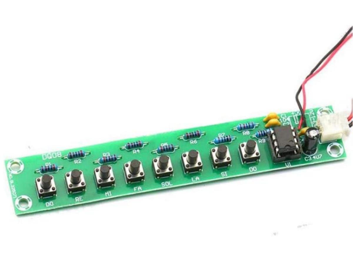
Now let’s take a look at how to build an 8-tone electronic organ circuit with the NE555 chip. The NE555 operates in astable multivibrator mode. Eight push buttons are used to control combinations of resistors with different values, which changes the oscillation frequency and generates 8 tones of different pitches. Then, the audio electrical signal output by the NE555 is transmitted to a speaker, and the circuit is complete. Here is the specific schematic diagram—you can refer to it to build your own electronic organ.

These resistors work with capacitor C3 to determine the charging and discharging time of the NE555.When you press a button corresponding to a small resistance value (e.g., SW7 paired with a 1 kΩ resistor), C3 charges at a faster rate. This makes the pulse frequency output by the NE555 higher, and the buzzer emits a higher-pitched sound.When you press a button corresponding to a large resistance value (e.g., SW8 paired with a 10 kΩ resistor), C3 charges more slowly. The output pulse frequency then decreases, and the buzzer’s pitch becomes lower.
The other buttons are paired with different resistance values, which also lead to varying pitch changes from the buzzer. In this way, you can make the buzzer produce different sounds by pressing different buttons. Do you understand this principle now?
FAQ
What does an NE555 do?
The NE555 is an 8-pin timing chip. By connecting external capacitors and resistors, it can realize delay, oscillation and trigger functions. It can directly drive small loads and is often used in timing and pulse generation circuits.
Is the 555 timer obsolete?
The 555 timer is not obsolete. It features low cost, simple circuit design and high reliability, making it a classic chip for electronic beginners. It is still widely used in simple timing and pulse scenarios nowadays.
What is the difference between NE555N and NE555P?
They have the same functions and parameters, only different packages. The NE555N comes in a through-hole DIP-8 package, while the NE555P is in a surface-mount package.
lm555 vs ne555?
Their basic functions are almost the same. The LM555 has better temperature stability, and some versions have higher voltage tolerance. However, the difference is negligible in ordinary application scenarios.