HX711 is a high-precision, low-cost 24Bit Analog-to-Digital Converter (ADC) chip specially designed for pressure sensors. It has a built-in voltage gain amplification function. By amplifying and reading the tiny voltage changes sent by the pressure sensor, it converts the pressure value into a digital signal and transmits it to the MCU. It features is wide operating voltage range (3.3V-5.5V), strong anti-interference capability and high precision, make it particularly suitable for small weighing devices.
Model
HX711
Working voltage
3.3 – 5V
Range
5KG
Accuracy
1g
A/D Bit Width
24 – Bit
Feature
Low cost, high precision, tiny size, low power consumption (suitable for battery power supply), two-channel input. used with electric bridge, it results in small measurement errors.
Two selectable differential inputs
On-chip low-noise programmable amplifier with selectable gains of 32, 64, and 128
On-chip voltage regulator can directly provide power to external sensors and the on-chip A/D converter
On-chip clock oscillator requires no external components; an external crystal or clock can be used if necessary
Power-on automatic reset circuit
Simple digital control and serial communication: all controls are input through pins, no programming is required for internal registers
Selects output data rates of 10Hz or 80Hz
Synchronous rejection of 50Hz and 60Hz power supply interference
Power consumption: typical operating current: <1.6mA, power-down current: <1uA
Operating voltage range: 2.6~5.5V
Operating temperature range: -40~+85℃
SOP-16 package
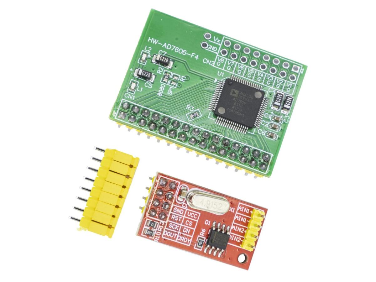
HX711 Amplifier
HX711 has built-in amplification function, but the voltage range it can amplify is very small, and it can only output in digital form
HX711 And Load Cell
load cell And HX711 Hookup
HX711 Circuit Diagram
What Is HX711 Used For?
HX711 can be used to make small, portable weight scales. Its low power consumption means you don't have to worry about battery life when powered by batteries. It can also be used to measure extremely small voltage changes (40mV) and output them to MCU.
Connect to load cellsensors to amplify the tiny analog signals output by the sensors.
Convert the amplified analog signals into digital signals through the built-in 24-bit high-precision A/D converter.
Provide a simple digital interface (such as SPI communication) to connect with micro-controllers, making it easy to read weight data.
How Does HX711 Work?
Certain materials exhibit a linear change in resistance when subjected to pressure. Through a specially designed electric bridge circuit, these materials can output a tiny voltage change (at the millivolt level) under pressure.HX711 reads this tiny voltage change,its amplifier receives the differential voltage signal from the sensor, amplifies it via internal precision circuitry, and then transmits the amplified analog signal to the chip's built-in 24-bit A/D converter. This completes the conversion from analog to digital signals, laying the foundation for subsequent data processing by the micro-controller.
Pin Definition&Interfaces
The VCC and GND pins are the power input ports of the HX711 chip respectively.
VCC : connected to a positive power supply of 5V or 3.3V.
GND : connected to the negative power supply (ground).
DOUT : data output port of the HX711 chip, which outputs the 24-bit data processed by A/D conversion.
SCK : clock input port of the HX711 chip, used to control the clock for A/D conversion.
Connect HX711 With Arduino Tutorial
HX711 communicates via a two-wire interface. It mainly connects to power pins, clock pin and data output pin. You can connect it to any digital pin of the Arduino board. For this project, we'll connect the data pin (DT) to pin 2 and the clock pin (CLK) to pin 3.
Connect the HX711 to the Arduino board according to the table or the schematic diagram.
LOAD CELL
HX711
HX711
ARDUINO
RED (E+)
E+
GND
GND
BLACK (E-)
E-
DT
Pin2
WHITE (A-)
A+
SCK
Pin3
GREEN (A+)
A-
VCC
5V
OLED
ARDUINO
VCC
3V3
GND
GND
SCL
A5
SDA
A4
Calibration
Arduino HX711 Example Code(Arduino IDE)
					#include <Adafruit_GFX.h>
#include <Adafruit_SSD1306.h>//OLED library

#define ADSK 2
#define ADDO 3

Adafruit_SSD1306 display(128,64, &Wire, -1);
//Set the screen size of OLED

long NormalValue;
long measuer(void);
long Weight;
void setup() {
  //Serial.begin(9600);//serial initialization
  pinMode(ADSK,OUTPUT);
  pinMode(ADDO,INPUT);
  digitalWrite(ADSK,0);
  display.begin(SSD1306_SWITCHCAPVCC, 0x3C);//Initialize OLED and set IIC communication address
  NormalValue=measuer();//store initial error value
}
void loop() {
  Weight=measuer()-NormalValue;
  //Serial.println(Weight/400);//send to serial,/400 is the parameter for convert pressure to weight,which need to adjusted gradually
  display.clearDisplay();//Clear screen
  display.setTextColor(WHITE);//Setting text color, monochrome OLED is invalid, but must have
  display.setTextSize(2);//Set text size
  display.setCursor(0, 0);//Set the starting X and Y axes of the text
  display.print("Weith:");
  display.setCursor(0, 20);
  if(Weight<0)// if the weight less than 0,will be a BUG if directly displaying on OLED
  {
    display.print("-");
    display.print((Weight/(-400000))%10);//thousands
    display.print((Weight/(-40000))%10);//hundreds
    display.print((Weight/(-4000))%10);//tens
    display.print((Weight/(-400))%10);//units
    display.print(".");
    display.print((Weight/(-40))%10);//decimal
  }
  else//weight greater than 2
  {
    display.print((Weight/400000)%10);
    display.print((Weight/40000)%10);
    display.print((Weight/4000)%10);
    display.print((Weight/400)%10);
    display.print(".");
    display.print((Weight/40)%10);
  }
  display.print("g");
  display.display();//Execute Display
}

long measuer()//read function,channel A,gain 128
{
    long Count;
    char i;
    digitalWrite(ADSK,0);
    Count=0;
    while(digitalRead(ADDO));
    for (i=0;i<24;i++)
    {
    digitalWrite(ADSK,1);
    delayMicroseconds(1);
    Count=Count<<1;
    digitalWrite(ADSK,0);
    delayMicroseconds(1);
    if(digitalRead(ADDO))
      Count++;
    }
    digitalWrite(ADSK,1);
    Count=Count^0x800000;
    digitalWrite(ADSK,0);
    return Count;
  }
Arduino HX711 Library
The Arduino HX711 Library is used to communicate with the HX711 weight sensor module. This library greatly simplifies the difficulty of using the HX711 module, enable developers to quickly implement high-precision weight measurement functions
The following are all libraries used in conjunction with Arduino and the HX711 weight sensor module
					#include "HX711.h"

// define HX711 DOUT and SCK pin
#define DOUT  3  // data output
#define SCK   2  // clock pin

// create HX711object
HX711 scale;

void setup() {
  Serial.begin(9600);
  // initialization HX711
  scale.begin(DOUT, SCK);
  // set gain
  scale.set_gain(64);  //A channel, gain64
  Serial.println("waiting HX711 ready...");
  // waiting module ready
  while (!scale.is_ready()) {
    Serial.println("HX711 unready,check the wiring...");
    delay(100);
  }
  Serial.println("HX711set!");
  Serial.println("ready to peeled");
  delay(1000);
  // reset
  scale.tare();
  Serial.println("peeled!");
  scale.set_scale(420);
  Serial.println("put the object");
}
void loop() {
    // reading weight
    float weight = scale.get_units(10);

    //gram
    Serial.print("weight: ");
    Serial.print(weight);
    Serial.println(" g");
    delay(1000);  // read per second
}
Initialization and Communication:Provide hardware connection initialization with the HX711 module, and implement the communication protocol between Arduino and HX711 (HX711 uses a custom 2-wire serial communication).
Data Reading:Read the converted raw weight data from HX711, supporting different gain settings (Channel A has 128x or 64x gain, and Channel B is fixed at 32x gain).
Calibration Function:Assist users in sensor calibration, calculate the scale factor through known weights, so as to convert raw data into actual weight units (such as grams, kilograms, etc.).
Tare Function:Implement the "tare" operation, that is, subtract the weight of the container to measure only the weight of the newly added object.
Data Processing:Provide simple data filtering or average calculation functions to reduce measurement noise and improve data stability.
Application
Household digital scales : can accurately measure human body weight, helping people keep track of their health in real time and used to precisely weigh ingredients, adding more convenience and quality assurance to people's lives.
Industrial production : On production lines, precise batching of raw materials is crucial to ensure the consistency of product weights. Meanwhile, in the product quality inspection process, accurate weighing can screen out products with unqualified weights, improving the overall quality of products.
Scientific research experiments : Scientific research experiments have extremely high requirements for data accuracy. The high-precision characteristics of HX711 make it an ideal choice for scientific research experiments. It can provide reliable data support for researchers, facilitating the smooth progress of scientific research.
IoT devices : HX711 can serve as a weight sensor in IoT devices, collecting weight data in real time and uploading it to the cloud. It can also provide accurate data based on weight changes, enabling intelligent production management.
FAQS
What Causes Data Drift In The HX711?
It may be caused by unstable power supply, temperature changes, mechanical interference, signal line interference, unstable reference voltage, etc.
How To Set The Clock Of HX711?
Ground the XI pin, and the HX711 will automatically select the internal clock oscillator with an output data rate of 10Hz or 80Hz. If an accurate output data rate is required, the external input clock can be connected to the XI pin through a 20pF DC blocking capacitor, or a crystal oscillator can be connected to the XI and XO pins.
What Format Of Data Does The HX711 Output?
It outputs a 24-bit binary two's complement digital quantity, which needs to be read by the single-chip microcomputer, converted to decimal, and then combined with calibration parameters to obtain the actual measured value.
Does The HX711 Need An External Power Supply?
Yes, the recommended operating voltage is usually 3.3V~5V. It needs a separate stable power supply, and it is better to keep the power supply consistent with that of the sensor and the single-chip microcomputer.